Making the Mendel Extruder Block from 16mm Hobby shop Acrylic block used for "Stamping"
First I printed these two pictures to stick onto the Acrylic so I can use the image to drill the holes.
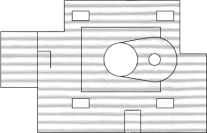

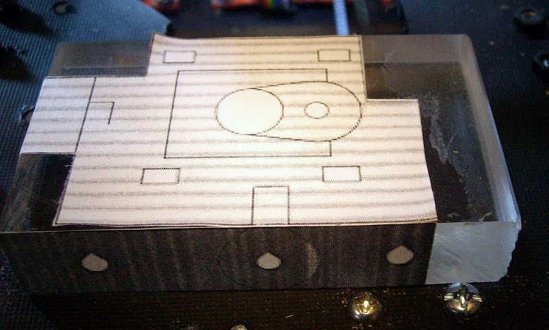
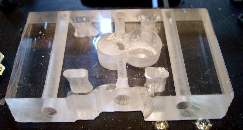
The holes were all drilled out to 3.6mm then 12mm for the motor center hole and 16mm for the blind bearing hole the two mounting holes were then drilled to 5mm to allow for movement to line things up.
Now I find my first problem with the Mendel instructions no mention of any gear required for the extruder its not listed in the Extruder BOM and to add to that there is no mention of any preparation required for the extruder motor shaft. What do I do.. now I'm sure its not just a friction drive off the motor shaft or is it..??
Its seems a pity that the Mendel instructions fall apart on the most crucial part of Mendel the extruder.
Oh hold on it might work without gears or splines as its turning the stepper threading the abs thru..
6 comments:
You have probably already got this one covered, but I didn't see it in the piccys.
Before printing out use the cad package to put a cross through the hole centers.
Then when you print it out the centers are already marked for you for drilling.
The centers are arguably more important than the circles. Particulalry where alignment across several pieces is needed.
Impressive progress with the hand making though.
You have to put splines on the shaft to drive the filament. Look here:
http://objects.reprap.org/wiki/Pinch_wheel_variations
Unfortunately, if you put a gear on it, you will have a larger radius and you won't have enough torque to move the filament, unless you use an oversized motor. The splined shaft turns out the be a simple, compact and efficient solution.
It didn't work without a gear or splines though it looked hopeful.
The WIKI instructions need to be corrected though so it was worth me following them to the letter if only to find the mistake.
AK47
I didn't use a CAD package..
I used 2 free viewers "3D print" to get an external dimension.
Then "E-Drawings viewer" position for best view to make from ~ then print screen/screen grab then "Paint shop pro 7" ~ paste as new, crop to external lines ~ resize using a dimension measured in 3Dprint ~ save file~ print
How ever I have found that by eye I get a better center to a circle than I do with a cross.
I did find an explanation for this some where online but I have forgotten where, else I would quote it.
On the site there is a series of tests that validate the idea of the eye being better than the mark.
Myccon
Thank you for that link.. I am right though in the instructions it has not been included?
Its not only not enough torque its not enough space.
As a gear just wont fit with the size the slots are.. and mine are a little bigger than they should be.
good work impressive none the less.
i will need to start to work on mine soon, but i am thinking that i will use a gearing systems in mine at the very least just to that i know i will have the torque that i will need.
any one out there have a diagram for a pinch wheel with a pully system in it.?
You can see as example my motor splines:
http://casainho-emcrepstrap.blogspot.com/2009/12/arrived-from-uk-my-new-nema-17-stepper.html
I have had a Beta blocker moment while the PVA glue was drying on my Spline cutter build. Its made from scraps of MDF of previous Darwin experimental parts. I have cardboard boxes full of little bits of MDf. Now waiting for more PVA to dry. As I have Three extruders Splines to do cut I'm making a re-useable spline cutter.
Dissidence
I have seen a nice looking yellow geard pinch wheel extruder on a recent post online will try to find a link for you.
Casainho
Thank you for the video link very impressed by the quality of your recent heated bed prints.
Post a Comment