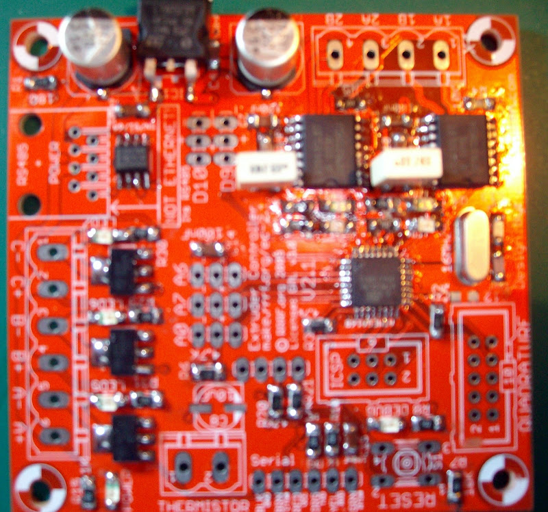
Before building the extruder controller V2.1 I examined the circuit diagrams of both versions 2.1 and 2.2
The bug with the V2.1 board is the reset switch is wired to the 5V supply instead of the Ground (0V).
To fix this Pins 3 and 4 of the reset switch will not be soldered or put though their holes on the board.
As Pin 3 is connected to Pin 4 internally inside the push button only one of the pins needs to be connected to Gnd.
This is done by scratching a patch of the solder resist on the ground plane off and soldering the pin to it. The other pin is bent up and then trimmed off to look neat..
Thus there will be no need to mess around unplugging power to cause a reset as you just press the reset button.
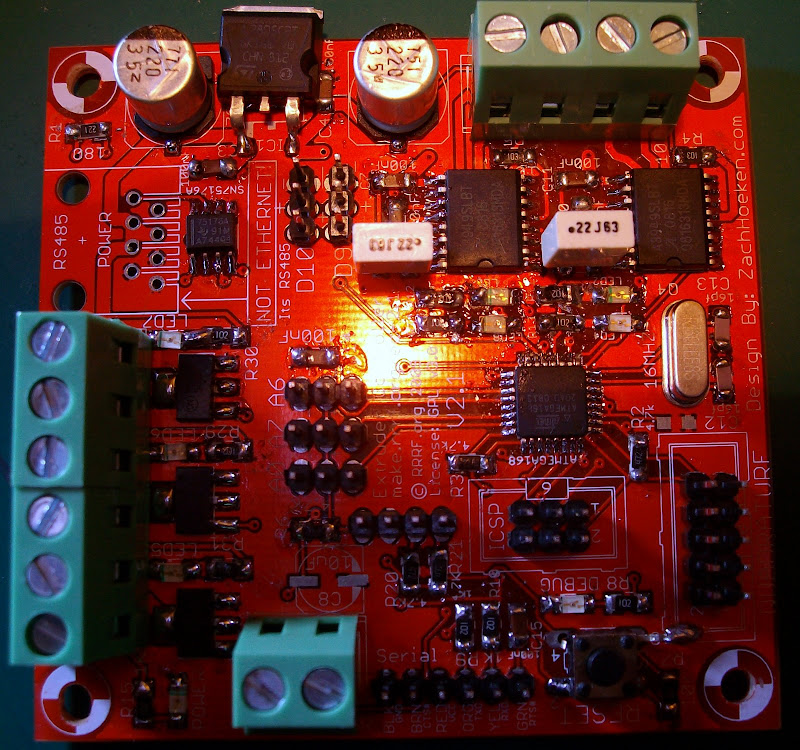
Please note I did not have an 0.22uf SMT devices so I used standard 0.22uf devices that I had in my capacitor draw.
This is the only part of the build instructions you need to change when following the on line step by step pictorial guide. If I can get my camera to be in focus for a close up I will add some pictures. Please note you only need to do this if you have the V2.1 boards the V2.2 have this bug fixed!! Better Pictures to follow hope fully.
No comments:
Post a Comment