Sunday, January 31, 2010

Nopheads small heated bed made from scrap.

It was Snowing today saw Nopheads new Heated Bed.. excellent Idea had to Make one.

As I knew I had almost all the bits even though they are all scrap.

Aluminium sheet from an DIY Radio I built in 1970. Magnets left over from Bathroom re-fit used 40 20mm neodym magnets to hold 300mm x 300mm wall tile / covers all the plumbing shut off taps. Tile is removed to access taps with a 4" glass sucker some puling.


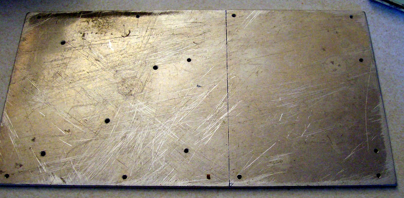
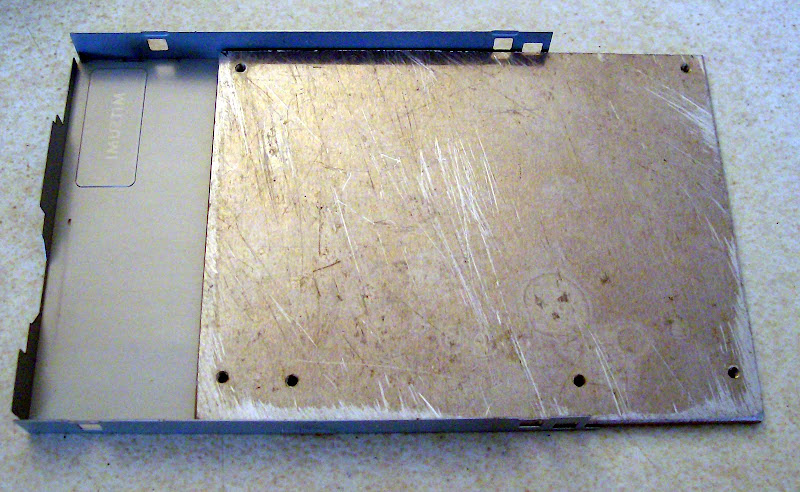
Thin steel plate for printing on an old Mitsumi 3.5" disc drive cover. So heated bed is cut to 130mm x 99mm inside dimensions of a disk drive.


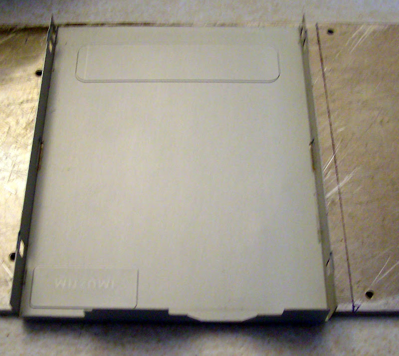
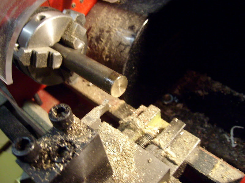
Cut the 3.3mm thick Aluminum plate to inside dimensions of a disk drive.
So heated bed will be 130mm x 99mm x 3.3mm.


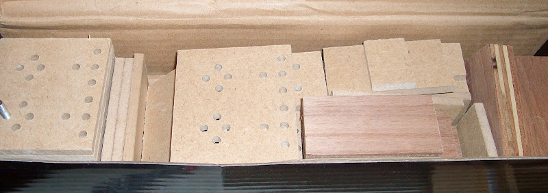
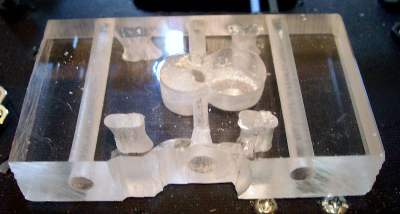
Stand off material had choice of Perspex ABS chopping board and MDF.
Decided MDF easiest least likely to be upset by temprature.


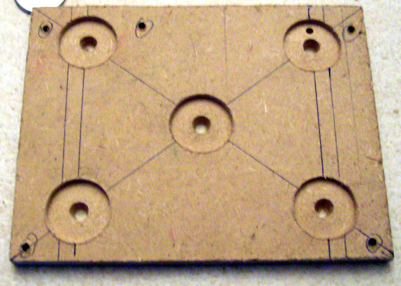
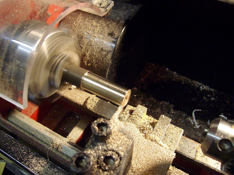
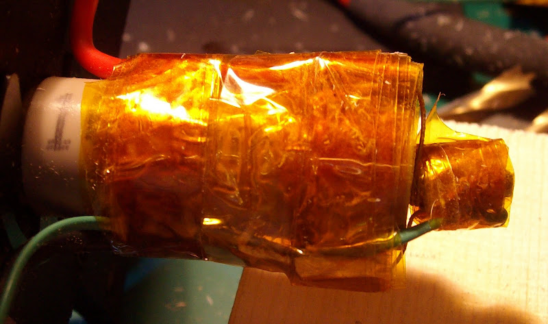
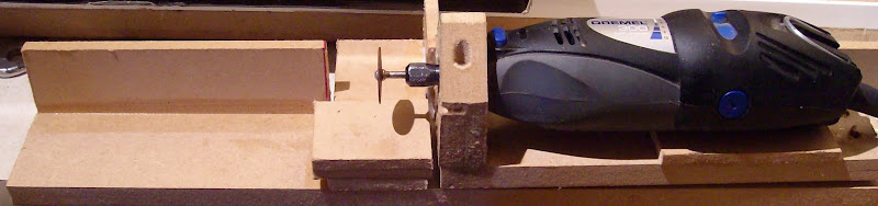
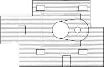
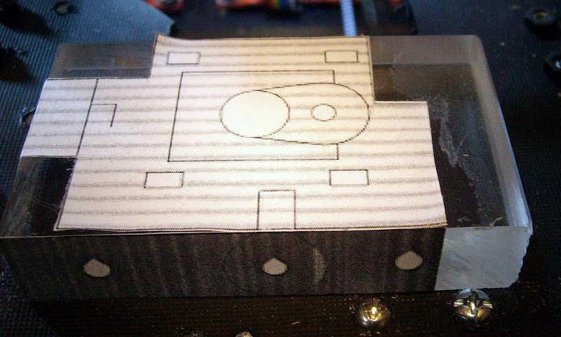
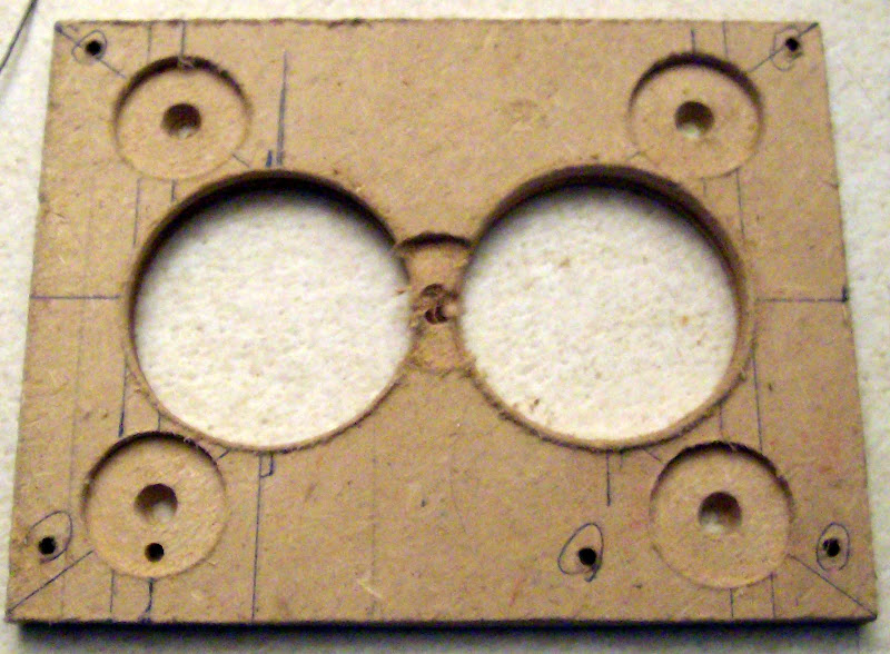
Blind 2mm deep 22mm holes for magnets found 2 2 ohm AL clad resistors checked with Nophead if he thought they were big enough. Marked out position drilled 2 big holes so the can mount through MDF.


Drilled and tapped aluminum for power resistors to fit. Screwed it all together added two 12mm thick strips of MDF as stand offs to mount heated bed to Mendel printing Bed.


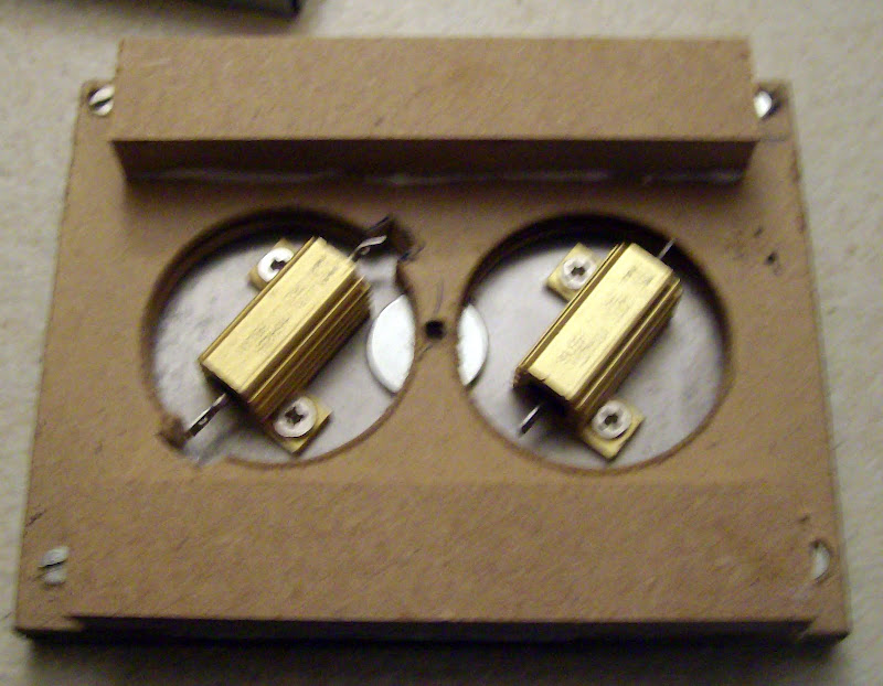
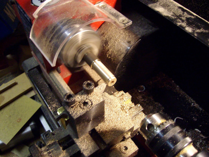
Have left two holes in plate for Thermocouples one will be fitted the other is for calibration.
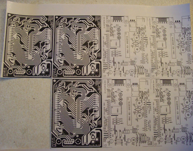
I will use the second extruder controller as a PID control for the heated bed.

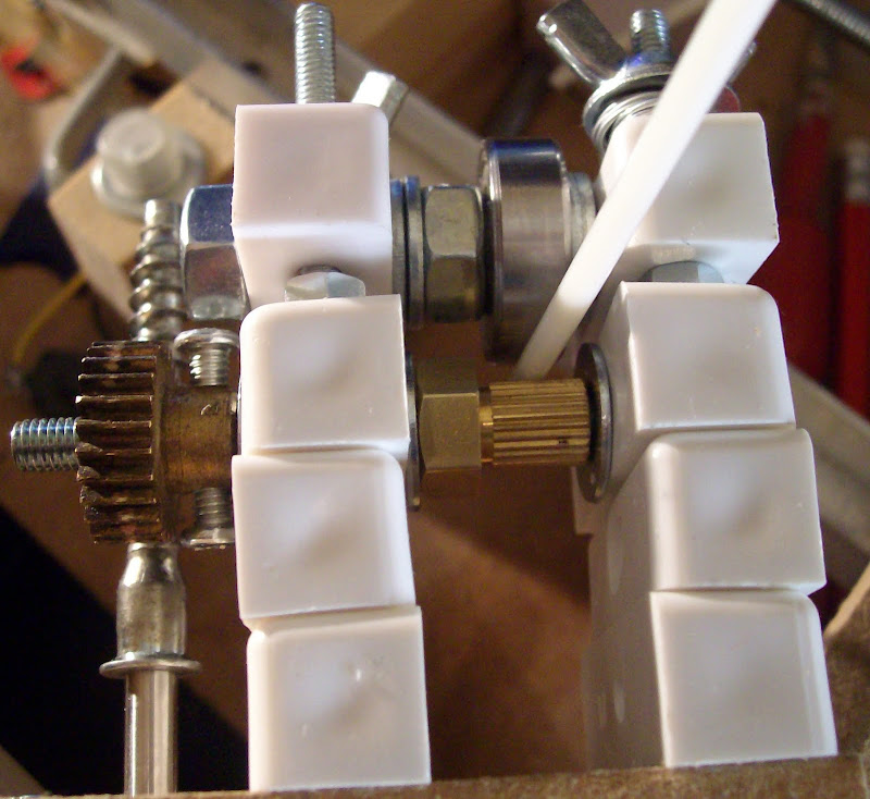
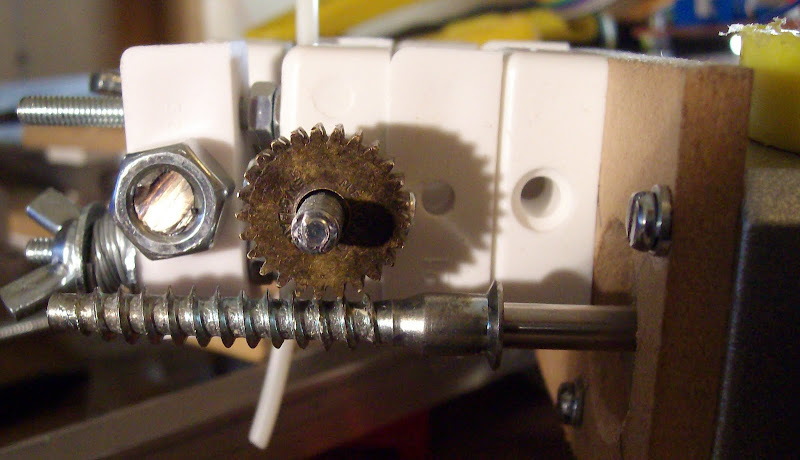
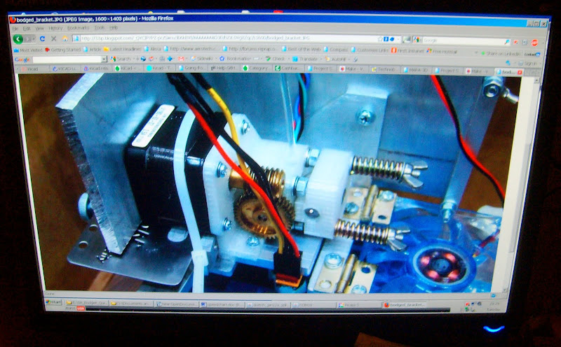
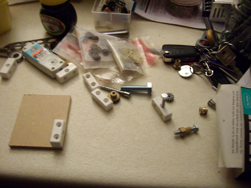
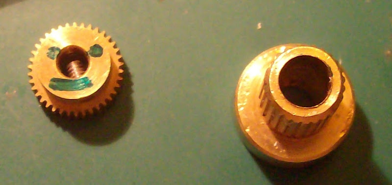
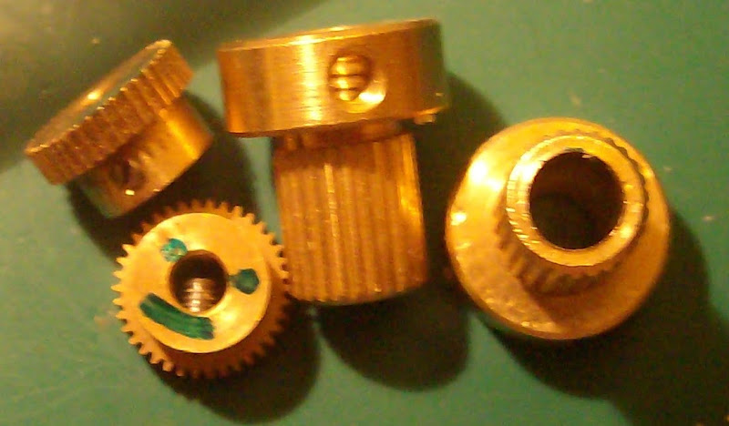
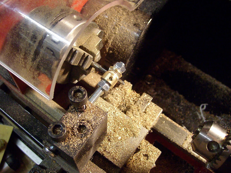
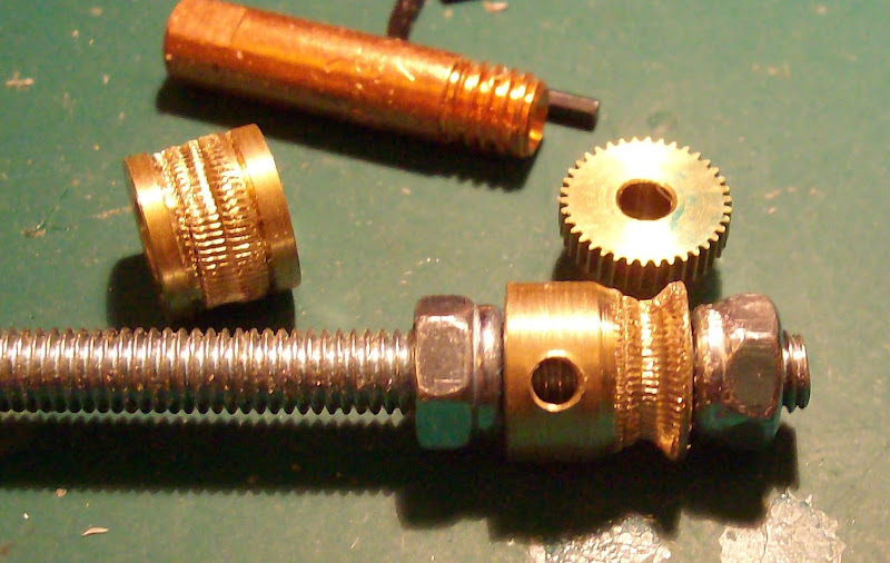
Still waiting for 4 Meccano worm gears to arrive so cant test my extruders yet.

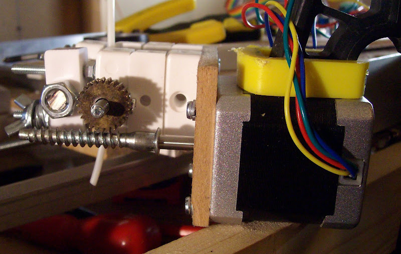
I will be setting up extruder controllers next flashing the boot then trying out the Software for temprature control on both extruder and Bed.

Thanks to Nopheads latest post I will have a heated bed without spending a penny.

Saturday, January 30, 2010

I'm going to MAKERFAIRE 2010!


Just got an email today confirming that I have a stand at the Makerfair in Newcastle to demonstrate RepRap in March 13th to 14th 2010!

Thursday, January 28, 2010

Wow Nopheads drive system is the killer App of RepRap extrusion drives!


The RapTruder Experiments could only be continued this evening as I only had time to make a template and two new versions of the RapTruder increasing the gap between the two blocks so I could try the Conrad shaft coupler as a drive gear and add a Skate bearing clamp with some fairly weak springs.

I used two Plastic blocks to join the welding rod works great!


Using The Flat pack Furniture Screw worm gear combined with a Meccano gear really works.


Please note I had to use a much bigger clamp to hold the RapTruder assembly down !!


Having seen this working now and seen the effect of just over a 3.5kg pull Maximum pull seen was 4.08Kg
I do not think Plastic gears would be strong enough to work.
I am seeing the MDF and plastic Blocks flexing as it reaches 2.9kg of pull.

The flexing makes the Furniture screw jump on the Meccano gear. The furniture screw is only a push fit on the stepper drive shaft it and it has not slipped yet.

The design really needs a shorter Worm gear; so that the assembly is not three plastic blocks high.

The optimum height is 2 Blocks only a proper Meccano worm gear will fit this height. I have not calculated the resolution the number of steps taken in the video clip was.

Taking 24464 steps.
Number of steps (-ve goes other way):


You can hear by the thump of the flexing and just how strong the pull is.

Very pleased with the results as it is only a lash up.

This is the BEST grip I have seen so far.
I am using the Conrad coupler as the drive.
This is very much the way to go the difference is so noticeable.

Having the spring adjustable grip and higher resolution are big winners.!!

I'm not sure if I can get this any better until I can stop the flexing.

Wednesday, January 27, 2010

Plastic Block RapTruder based on the "No compromise Extruder"

Based on Nopheads "No compromise Extruder" design.


So how on earth do you make something like Nopheads  "No compromise Extruder"


It was this message left by


Casainho said...

Thanks!!! I don't have a lathe but I am trying understand what could I do with it.

I was curious on how to make the worm pulley since NopHead had very good results using it.
I wish I could make my own gears, and make the same extruder as NopHead...


Now there's a Challenge  !


This is how you do it without special tools without a Worm Gear with one Mecano gear!!
 
Please note you can go and buy a mecano worm gear ~ I just have no money so I have to improvise even more.  
 

I have another Idea for a no money solution not sure if this will be strong enough.
The big white tray drive gear out of a 5.25 CD drive and a 12mm bolt.
 
The 12mm bolt is the worm for the CD drive tray gear. 

Any way here is the result of the initial idea.
It will need some more work but hey it works.


I spent more time looking for my other big grey gear like I have used on the Mendel Z axis drive.

This would also work and mean that you use all 5 gears as they come in packs of 5 for £1:50 ish.

Any way here is the first Video of it working time from Idea to this stage about two hours.

With a Beta blocker nap in between making and posting. 

Will make another version tomorrow as another Idea to go from.    
     

 End of Plastic Block RapTruder Part 1 stay tuned for part two

Tuesday, January 26, 2010

Mendel gear creation gears that failed to get a grip.


A pictorial record of gear creation gears that failed to get a good grip. 


By the way the face on the gear was an atempt to trigger face recognition on the camera.


It failed to get auto focus to work any better. 


A length of 1/2" brass kindly left by the previous owner of my house.


My second use of the floating steady with more olive oil added to the fingers to stop them squealing.


Cutting the brass bar to a useable lenght.

 
Brass is incredibly tough to machine it holds on to it tries to hold on no matter how hard you cut into it.


Cut to a size ready to make two of AK47's "worm gears"


From 12.5mm to 10mm the incredibly slow way.


Eventualy ending up with this


Making the worm using a 3mm tap lathe turning at about 200 rpm.


ready to test.


Free hand dremel drilling lookls ugly but works  to save making a new block to hold the variety of gears.


Well my badly made worm fails to grip any better back to the drawing board as they say..

Thus the splined shaft remains the best gripping extruder drive wheel that I can make


Experimenting with video with a short film on how not to make a worm gear.

At least a day wasted as my extruder is still no better than my first attempt!!

Glad I chose the Electronics apprenticship when I was offerd the choice of mechanical or electronics at my interview. 
Taking a working steam engine as well as a simple dial in adding computer to my interview meant I was offerd both. I chose the right one!

Sunday, January 24, 2010

making Mendel element on Welding tip and Torque test video


An in focus picture of the shorter Extruder with long wedding tip made in December.


Here is the New longer Peek insulator with the shorter welding tip.


The insulator anti twist securing hole drilled out read or a 3mm screw.


With the screw fitted and a bevel to aid the alignment of material being extruded this was made using the tip of a 22mm flat wood bit.


The brass inserts were removed from a standard plastic 3A chocolate block attached to my last 7 ohms of cotton covered nichrome wire.


The red cable is attached to one end of the element and taped to the Peek insulator using 200C heat resistant Kapton tape its ready to wind the element.


Element wound ready for the Black wire end of the element to be taped up.


Taped up twice on the long Peek insulator.


The end on view now with a K type thermocouple slid in under the layer of Kapton tape its the green wire.


Last months heated barrel looked like this before the high temprature black self amalgamating tape was put on.

Now for my second Video where I miss getting the scale showing 2Kg for the second or third time each time destroying two foot or more of ABS welding Rod as the splines eat it up as it starts to slip and yes it had already stated to slip by the time I got the camera to focus on the digital scales Ahhhh. We decide to give up before we had got any more frustrated by trying to film it.


Testing the new splines shaft in my perspex clone of the Mendel extruder block with 3mm ABS gave a maximum of 2kg of pull measured before the ABS starts to be eaten away by the splined shaft.

Now we know that Wade has achieved 5.5kg of pull without slippage.

So whats was the difference.

Nophead is using the AKA47 "worm" pulley. It is 15mm OD, ~13mm ID using an M4 tap

And has suggested halving the ID to 6.5mm and using a M3.5x0.6 tap with an OD of 10mm

The other difference is both Wade and Nopheads extruders have a spring tensioner to control the pressure of the grip.

Where as the standard Mendel extruder has the pressure set by setting up the gap to be 2.5mm between the bearing and the splined shaft using a drill.

I tried using a 2.4mm drill this had no effect on the grip.

Using the AK47 "worm" pulley makes a lot of sense as it will be gripping more of the ABS.

So tomorow that will be my next Job.

Many thanks to Nophead for all his marvelous pioneering work on extruders and extremely detailed blogs.

Not forgetting AK47 and his great "worm" pulley blog entry the next task is to make a new acrylic block tat can incorporate the "worm" pulley

Saturday, January 23, 2010

The Spline cutter worked great

Cutting the splines on the extruder stepper motor was very easy with the spline cutter pictures. below.


The first set of 11 0.7mm splines were cut with a  4mm spacer in place on the dremel spline cutter with 36 steps between each spline the spacer was then removed and another 11 cuts were made making the splines 4mm longer.


Testing the Stepper drive.. and posting my 1st YouTube video.

Tuesday, January 19, 2010

Wow my first Toner transfer Home made PCB that is Usable !!!!!!!!

For a while I have wanted to try a different way of Toner transfer PCB making that I had read about on line. 


I found this single sided board Arduino Single-Sided Serial Board (version 3) as I have the old chip from my Arduino Decimila that's now been converted to a Arduino Demiglove I could do with a new board for the old chip.


I have tried all kinds of colour photo paper in the past followed several different peoples blogs on how you iron on your picture the soak it in water and gently rub the paper off.. 

Well no matter how careful you are Gently rubbing the toner It comes off leaving areas of track that get over etched with bits of track missing.

So reading about this other method that sounded like it might work I though I would give it a try to day as I had used some Computer labels I had the backing sheet to try out.

What you do is you print on the backing sheet of the computer labels.


I have not had any success with laser Iron on transfer. I was not as pedantic in my cleaning of the board just a quick scrub with a green plastic scourer. 
Then I Ironed on the printed image on to the board.. leaving the iron on for about 1-2 mins no rubbing just resting on the label removed the iron. Tried peeling the corner up - to my surprise every part of the toner image was left on the board. 


A new use for Arnie the £10 PID control HOB  keeping the etch ant warm to make the etching quicker. I set the P.I.D. controller to 50C put a metal case on the hob then the plastic etch tray I found I needed to cover the tray to try to keep the heat in eventually getting 40C popped the board in to etch went away and left it etching wile I set up the Spline cutter.


I took it out slightly too soon as there are a few little patches that are under etched but it is by far better than any previous toner transfer etch result I can see that this board will work It will not need any track repairs.


The labels I have are the cheapest ones you can get from a pound shop so I think any kind will work just fine.

Very very pleased with this result as I have several CCT designs I want to try ~  I hate using the non solder prototyping boards even though I have just bought my first one. I prefer to go from design to board as it has always been the fastest route to have a working demo board to get funding from Directors or customers to start a new project.

PS my laser toner is on its last legs as well I need to put a new one in.. I have one but just want to get every last drop out of the current one first. The toner on the board was a devil of a job to get off and nail varnish remover did not remove it so it was scrubbing with the same old green plastic scourer to get the toner off.

Monday, January 18, 2010

Mendel Spline cutter for Mendel Extruders made from scrap MDF

.
Mendel Spline cutter for Mendel Extruders made from scrap MDF.


Its made from scraps of MDF of previous Darwin experimental parts.


I have cardboard boxes full of little bits of MDF.

The spline cutter has three stepper Splines to cut so I have made it as a bit more of a permanent fixture.


The MDF holding the Real Dremel (the Dremel look alike is on the Bertha CNC) the MDF  was originally a Stepper motor mount on one of many experimental Darwin builds i have at least 4 or 5 boxes of MDF scraps like this.


Blogging this while I'm waiting for the second lot of PVA glue to dry.

Making the Mendel Extruder Block

.
Making the Mendel Extruder Block from 16mm Hobby shop Acrylic block used for "Stamping"


First I printed these two pictures to stick onto the Acrylic so I can use the image to drill the holes.


The holes were all drilled out to 3.6mm then 12mm for the motor center hole and 16mm for the blind bearing hole the two mounting holes were then drilled to 5mm to allow for movement to line things up.


Now I find my first problem with the Mendel instructions no mention of any gear required for the extruder its not listed in the Extruder BOM and to add to that there is no mention of  any preparation required for the extruder motor shaft. What do I do.. now I'm sure its not just a friction drive off the motor shaft or is it..??


Its seems a pity that the Mendel instructions fall apart on the most crucial part of Mendel the extruder. 


Oh hold on it might work without gears or splines as its turning the stepper threading the abs thru..