I have not done much this week ;-(
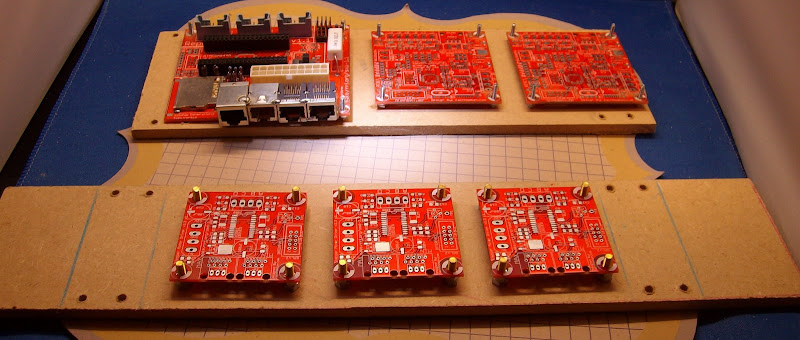
I did finish making the 3 Stepper Motor Drivers v2.3, the 3 10way ribbon cables, re-working the 1.1 motherboard and Extruder controller V1.2 (Removing the Ethernet RJ45 connectors and AT power connector) I didn't read/notice the Extra notes on modifying these boards for Mendel till Tuesday.

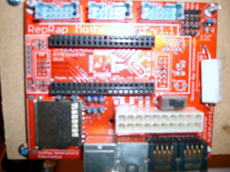
Bit of a pain as in removing the Ethernet RJ45 connector on the extruder controller I damaged a track hence on the motherboard I have left one of the fully sealed in RJ45 connectors on the board. I fixed the track with some wire wrap wire as I have run out of Verowire now. Destruction of the RJ45 connectors is the only safe way to remove them with the exception of RJ45 connectors that a fully moulded in plastic where you cant remove one pin at a time hence the damaged track on my Extruder controller.

I also took the time to Fix one of the first Stepper Motor Drivers v2.3 were i killed the chip when setting up the Baby Bertha 3D platform (nothing blogged on Baby Bertha yet.!). Rather than dremel the leads like Nophead did I lifted each pin in turn using the point of my tweezers so I have the smt chip off intact to play with later.
I will steal the 20V PSU from Bertha CNC as the proper 32V power supply shown here for Bertha CNC arrived in November but I never fitted it.

I will then use the 20V PSU for Mendel as I know the Stepper Motor Drivers v2.3 worked OK with it on my Baby Bertha experiments where I took the voltage up to 29V without problems.
Testing the Stepper Motor Drivers v2.3 using my modified Arduino Decimila that I have upgraded to an Arduino Demiglove by replacing the Atmel ATmega168 with a Atmel ATmega328 I made a little Veroboard break out board to do this.
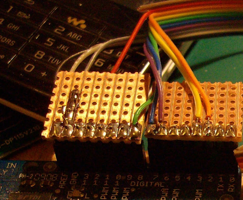
| 1 | N/C | Brown | No Connection | |
| GND | 2 | GND | Red | Ground. |
| 2 | 3 | Step | Orange | Step |
| 3 | 4 | Dir | Yellow | Direction high forward, low backwards. |
| 8 | 5 | Enable | Green | Active low Enable |
| 7 | 6 | Min | Blue | 'min' sensor |
| 6 | 7 | Max | Violet | 'max' sensor. |
| GND | 8 | GND | Grey | Ground. |
| GND | 9 | GND | White | Ground. |
| GND | 10 | GND | Black | Ground. |
Test code with the altered pin configuration for use with the Arduino Demiglove and Veroboard quite a funny reaction from Midge wondering where I had connected a speaker so I had to explain it was the stepper motor playing the Happy birthday tune. By the time I had tested the 3 new boards and the fixed boards it had lost a little of its original charm thou.

I changed the 3 lines defining the pins in the listing. (Shown in bold) to work with the Veroboard break out board.
The original of this code is from the reprap builders blog by Zack or Makerbot; I think as now cant remember where I found the listing.
I thought it was on Stepper motor build instructions but it wasn't there. So I have listed the whole thing!
#define stepPin 2
#define dirPin 3
#define enablePin 8
#define minPin 7
#define maxPin 6
void setup()
{
Serial.begin(19200);
Serial.println("Starting stepper exerciser.");
pinMode(stepPin, OUTPUT);
pinMode(dirPin, OUTPUT);
pinMode(enablePin, OUTPUT);
pinMode(minPin, INPUT);
pinMode(maxPin, INPUT);
digitalWrite(minPin, HIGH); //turn on internal pullup
digitalWrite(maxPin, HIGH); //other pullup
digitalWrite(dirPin, HIGH);
digitalWrite(stepPin, LOW);
digitalWrite(enablePin, HIGH); //disable
calculate_tones();
}
void loop()
{
Serial.println("Forward!");
digitalWrite(dirPin, HIGH);
play_song(maxPin);
delay(500);
Serial.println("Reverse!");
digitalWrite(dirPin, LOW);
play_song(minPin);
delay(500);
}
boolean at_switch(byte pin)
{
return !digitalRead(pin);
}
#define TONE_COUNT 16
float frequencies[TONE_COUNT] = {
196.00, //G 0
207.65, //G# 1
220.00, //A 2
233.08, //B- 3
246.94, //B 4
261.63, //C 5
277.18, //C# 6
293.66, //D 7
311.13, //D# 8
329.63, //E 9
349.23, //F 10
392.00, //G 11
440.00, //A 12
466.16, //B- 13
493.88, //B 14
523.25, //C 15
};
int tones[TONE_COUNT];
#define NOTE_COUNT 25
int notes[] = {
5, 5, 7, 5, 10, 9, 5, 5, 7, 5, 11, 10, 5, 5, 15, 12, 10, 9, 7, 13, 13, 12, 10, 11, 10
};
void calculate_tones()
{
for (byte i=0; i
tones[i] = (int)(1000000.0/ (2.0 * frequencies[i]));
}
void play_song(byte switchPin)
{
digitalWrite(enablePin, LOW); //enable
for (byte i=0; i
{
if (!at_switch(switchPin))
{
play_note(tones[notes[i]], 300000);
delay(10);
}
}
digitalWrite(enablePin, HIGH); //disable
}
void play_note(int note, long time)
{
int count = round(time / note);
for (int i=0; i
{
digitalWrite(stepPin, HIGH);
delayMicroseconds(note);
digitalWrite(stepPin, LOW);
delayMicroseconds(note);
}
}
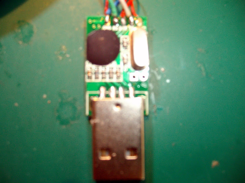
Also this weekend I'm going to try making a CA-42 Nokia lead into a USB comms lead for the 1.1 mother board.

When you take the cover off my picture here is the best of many taken trying to show the silk screen that is neatly labeled with the signal names going to the Nokia plug not a bad buy for £0.99 on EBay or $1.62 including P&P I will cut up a USB cable to re use its wire to connect to Veroboard with a 0.1 female connector to go to connect to the pins on the Sanguino mounted on the Mother board.
1 comment:
Can you tell me which ebay seller you got your cable from.
I ordered the cheapest one I could find a month ago from topvshonw for $2.98 shipped. Unfortunately the model i got was in a one piece rubber housing that was formed around the circuit.
In ripping it apart I managed to pull the cable leads of the board. Unfortunately my unit is not as nicely built as yours looks and the only labels on the pads are sequential pin numbers 1 through 12. There are several unpopulated capacitor and resistor locations. On the plus side it looks like there may be a spot for a max232 type chip but I haven't really investigated that yet.
I'm sure I can scope out the signals and wire it back up, but If I buy another I think I'd like to try the one you have.
Post a Comment