Monday, October 27, 2008

Stepper Motor mounts for Z and Y Axis

The motor mounts and he drive couplings have evolved from the X Axis discovery's lessons learnt from the design it as you build it method I used for this project.
On the X axis these problems were:-

  • Stepper motors too small to drive weight
  • Home brew stepper motor controllers more expensive to buy than Zacks RRRF full kits.
  • 5mml studding had too much flex was hard to buy perfectly straight straight lengths.
  • Alignment of Stepper motors to studding drive is very difficult.
The solutions were:-
  • Buy Stepper motors from Bits from Bytes - Excellent dual ended drive shafts.
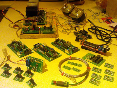
  • Buy all future electronics as complete kits from Zack at RRRF nice and easy.
  • Upgrade studding from 5mm to 8mm re arrange the structure to accommodate 8mm.
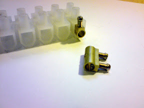
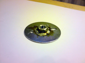
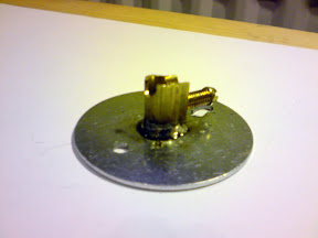
  • Improvise a drive linkage tried using tried springs, clear hose pipe, then used the holes left from a hole cutter which was refined to using big washers, nuts and 60 Amp chock block.
Here are the pictures of the final result of these changes.

From Blogger Pictures

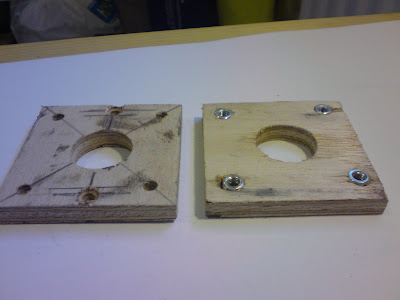
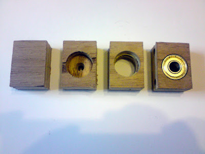
Motor mounting blocks with captive nuts the large hole is 25mm the four smaller holes 5.5mm they are counter bored with 8.5mm to a depth of 2.5mm the plywood is 6mm thick.


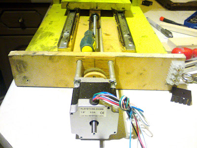
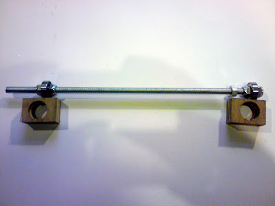
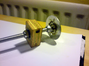
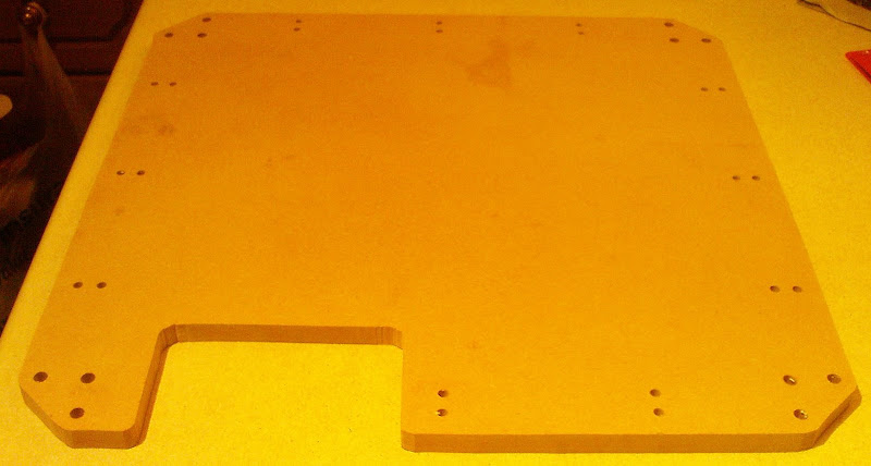
A picture of the x axis drive its using the MDF motor couplings made from scrap floor laminate you can see how i needed to cut a slot in the base plate to accommodate the 8mm drive and bearings.

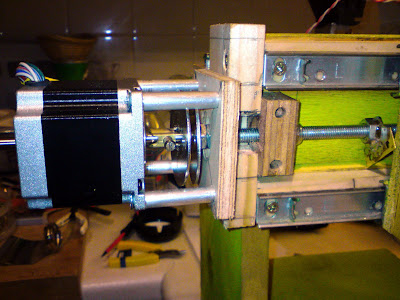
The Y Axis in close up detail motor drive coupling and bearing shown with the picture of the Y and Z axis to the right.

Sunday, October 26, 2008

Details of the drive shafts bearings & motor coupling

Rep Strap Bertha is screw thread driven using 8mm studding with roller skate bearings and large washers for anti shake drive coupling.

Here are the roller skate bearings mounts made from 18mm plywood, it is drilled with a 22mm hole 7mm deep then a 19mm drill is used to complete the hole this provides a retention shelf for the bearing to rest on.
From Blogger Pictures


Here is the assembly of the Y Axis drive shaft please note I used Adrian Atkins tip of using 22swg solder to wrap around the thread to stop any bearing wiggle the bearings are positioned with Nylock lock nuts.
From Blogger Pictures

The steeper motors a connected to the drive shafts with anti shake couplings made from large washers a 1/2 60 Amp terminal 8mm nut 4mm not and bolt. The washers are bolted together for drilling and filling.

These coupling parts are then assembled using a 45W Weller soldering Iorn positioning the nut with a bolt and the terminal with a 4mm bolt, spring and nut.

The Drive coupling can now be Nylock nutted on the the end of the Y axis Shaft.

Monday, October 20, 2008

Steel frame Kit orderd

Ordered the Steel Frame Kit from Bits From Bytes as because I don't know any suppliers up in the north west, did not have time to find a supplier of the raw steel it was a lazy option I guess.
(I know plenty of places in the South east 240 miles away ~ the main draw back of relocation is loss of local knowledge)

Anticipating the arrival of this kit I used a jigsaw to cut the Darwin print platform out of MDF tonight.
From Blogger Pictures
As I now have almost two full sets of working electronics so I though might as well have two set ups to play with; A wooden Darwin driven by Sanguino and the Rep Strap Bertha driven by the Arudrino.
From Blogger Pictures
I also have a 500mm x 500mm x 500mm CNC in the process of being constructed based on the experiences of the Rep Strap Bertha build. Still using draw slides but 24" heavy duty ones some thing like a 50kg load capacity per pair. I will wait for the new new Stepper Motor Driver v2.0 PCB kit from Zack to drive this beast.

The XYL is correcting my wording from the other room now. I need to get a digital camera that's a little better than the one on my Smartphone to put some pictures up of these efforts.

Saturday, October 18, 2008

Plywood Extruder part 1

The extruder how can I make one cheaply:
Search the RepRap Wiki to find a set of drawings for the extruder parts.

The answer had to be using hard wood plywood from the local Bodge It Quick store:

For the 10mm thick parts use 9mm hard wood ply.
To get the 15mm thick parts glue 6mm to 9mm hard wood ply.
To get the 25mm thick parts make it 24mm with 18mm glued to 6mm hard wood ply.

As these parts were designed to be printed or lazer cut not made from wood.
Planning the way you start to fabricate them is required.

The extruder design I am opting for the direct drive extruder system.
As I alredy have the optical encoder from Zack at the rrrf built and working.

The direct drive extruder has still two designs one of Adrians and on from Nophead.
The difrence being Adrians retains the drive gearing and Nopheads has this removed.
I alredy have bought the two packs of 5 Geenbank gear wheels seems a pity to waste them.
But Nopheads extruder is simpler for not having them going for the Kiss system (Keep It Simple Stupid) I can always add the gearing later if its needed saves at least making the L shaped part that holds the gears.

So I can scrubb the L shaped 25mm /24mm thick part.

Parts list is now reduced to the screw side of the extruder and the polymer guide part of the extruder. The Motor mounting bracket, the extruder assembly mounting bracket, the motor coupling.

Router in clasped firmly in my hand its off to the shed....