Sunday, November 28, 2010

Bodge & Midge Visit Fab Lab Manchester.

Its time to write a few things up and share with you the wonders of  FabLab Manchester


As you know I have been making drawings of both of my Re-Strap renditions so that others can build their own Repstrap that works without having to re-invent the wheel to solve the problem of not having printed parts to start with. I have been taking at least a week to make all the parts from my drawings it gets tedious you end up with huge collections of sometimes useless parts. I have piles of failed ideas filling boxes in the workshop.


Above Right MTM multifab has a similar design principal to http://blog.ultimaker.com/ a small box sliding on two cross hair bars.

So I thought I would save some time if I could make use of the equipment at FabLab Manchester.

The Laser cutter in particular which is the most popular tool in FabLab so there seems to always be a Que for it.


I have now used the  Dimension 1200es Series 3D Printer It has produced an interesting result as seen in the pictures.


The most interesting stuff is the support material that is said to be ABS + additive. Its feels hard snaps like wafer biscuit its a dull brown in colour it behaves like what I imagine extruded sugar would be like brittle and crunchy turning to dust.t usually is dissolved in an heated bath of water soluble solvent taking several hours to be dissolved.

Dimension 1200 Print options for Wades extruder body


Low density 30.45^3 cm

High density 39.00^3 cm

Solid 44.37^3 cm

Support material


Basic 11.37^3 cm

Sparse 11.66^3 cm

Smart 10.23^3 cm


I Opted for the lowest density with sparse support material as you pay £0.33 per cubic cm for both materials plus VAT so the extruder body and Clamp was £18.05 ~ Print time on the 1200es was 4 hours.

The amount of support material used by the Dimension is huge Things printed by RepRap without any form of support material need to have support material in the Dimension. Having seen the results of RepRaps and a Dimension 1200 I think Adrian's RepRap project  has really cracked the nut particularly as RepRap results are constantly getting better.


Any way I printed Wades Extruder body and clamp un-fortuantly the resultant print has an extra part to it where there should be a hole there is a thin membrain of ABS. This is not visable in any applictions I use to view STL files. Im sure that when I loaded the STL file before it was printed the hole was a hole all the way through.


You can see I am going to have to drill out the extra material that is a 1mm thick membrane to make use of the part..

I have also used the Laser cutter its a neat tool I have save a week of sawing chiseling and drilling for each revision of my drawings I have made. As promised to Sebastian Ballard I will not blog the making of Huxley seedling here until I have put it in the ReprapWIKI.

Picture of Repstrap Mendel parts / Drawings Laser cut based on my Mendel 2009 build.


Midge took a few pics of Fab Lab so here they are.


I also introduced some of the other users to REPRAP and HydraRaptor ending up having to explain what a NOP was.

Strange until that point I had not given much thought to it.. as we all know  NopHead is far from being a Nophead.
I also discovered that its really only us old hand coding or in your head assemblers form the era of and Nascoms / 8080s - Z80s that even know what a NOP is.

NOP in assembler is the instruction or mnemonic for No Operation Performed

Monday, November 22, 2010

Been busy.

Dawing and re-Drawing my new Repstrap Huxley and Mendel designs so I'v not had time for taking pictures Blogging, FaceBook, Linked-in or Twitter.

Next week I think I should have some pics. If all goes well this week I will be blogging some pictures of my results next week. I will be posting the drawings first on the reprap Wiki.

Sunday, October 31, 2010

New Hot End ~ Peak insulator melts~ as Thermocouple fell off

The idea was to have a new changeable extruder tip to allow for extruder die swell tests and a swappable 0.3 mm tip.. but alas changing / fixing some thing that's not broke or applying instant design usually fails.


From Blogger Pictures

So my insulator that has extruded by now over a 1lb of ABS I need to remake it was all going so well ;-(.


Lesson learnt do not rely on Kapton tape to hold a thermocouple onto a heater block.


At least I know the heater block works OK.. showing heater bloc and 2 copper 0.6 welding tips and a brass copy with 0.3mm hole.

Aside from that my Evolution saw ate itself earlier today not a good day..


The part on the Right is all that remains of the blade guide the part on the left is part of the blade safety cover.


It looks like the blade guide a two prong fork thing came lose it was shredded by the blade then  flew around blade cover cracking it and the blade safety cover open and the motor mount is also split open. Needles to say it did fail safely. Not happy that it failed though.

Saturday, October 30, 2010

Before and After fixing Y axis wobble

From Blogger Pictures
After chasing my tail the problem of the Y axis instability is solved.

Watching the Y axis I was convinced that I was losing position on the Y axis due to belt slipping jumping on the drive gears..

1/. So I rebuilt the Y stage and the X stage using linear bearings ... The gain was a significant noise reduction Y position wobble still there strange...

2/. Replace the Y belt for 10mm 5mm pitch wire strengthen belt replacing the old 4mm wide xml rubber belt..

No change...


3/ Adjusting the current drive on the Y axis stepper controller threw up a strange effect it was a little like tuneing the stage a small band on the current adjusting resistor rendered zero Y positional wobble.
Problem solved sort of... spent the night thinking about how this could be..

4/. Looked at my firmware again then at the  "Tonkip FiveD" code noticed that disable stepper after a move had been commented out. Thought about it a little remembering stepper tests and how the steppers jerked as the start up.
Modified my code by removing disable steppers code. As I have used all my Sanguino pins Ive lost the power on off pin. So in the time out code that usually switches the power off I have now got disable steppers code. I also adjusted the M80 instruction to disable stepper.

So after a print I now send an M80 

Y axis positional wobble  was caused by the stepper motor jerking as it was restarting for each move also explaining the ability to tune the effect out by adjusting the current. The belt movement is now not jerking but as its kept taught.

The side effect again is the whole thing is quieter than my laser and ink jet printers where as originally you could hear it in the house 14 meters away from the fully insulated  home office.

Im still struggling slightly with making rafts tht stay down on the perspex
Its ok for things like a Nopheads belt drive gear and Eriks standing-mini-mendel-vertex with an 8mm border. However if printing some thing flat I still get warping if any one could sugest the best thicknes of the first layer of the raft and the height of the next two layers to prevent warping that would be great start. Im using repsapper.

Im still trying to get a heated bed to work

Wednesday, October 27, 2010

Quick Problem update

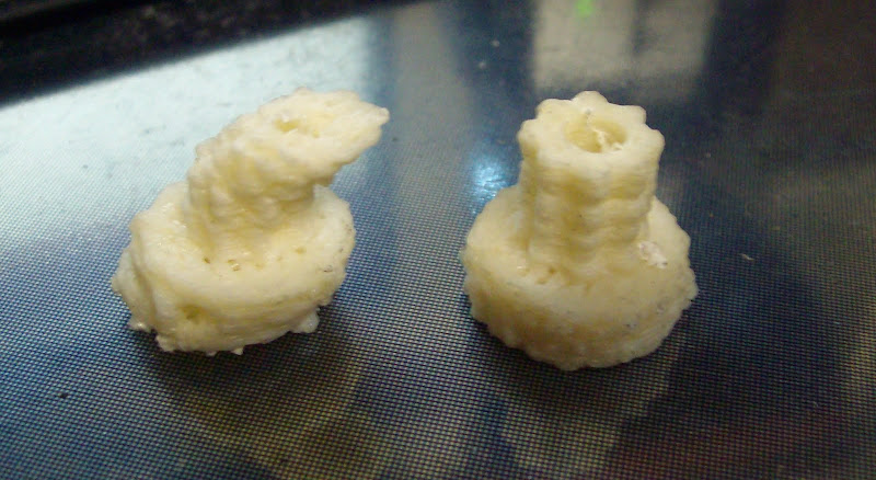
Problem after problem gradually solved one after another..

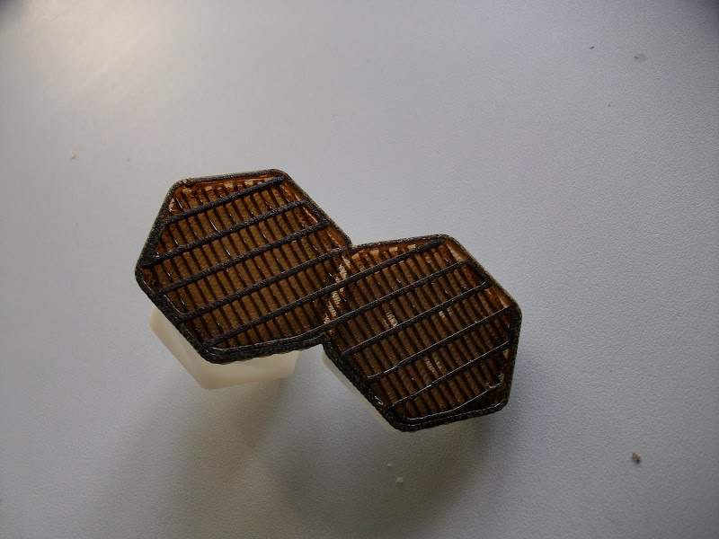
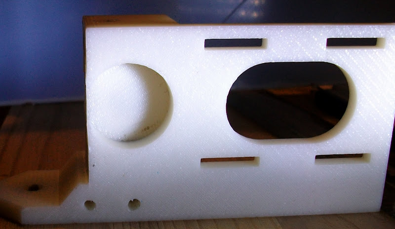
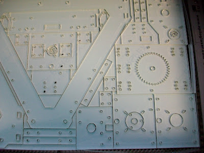
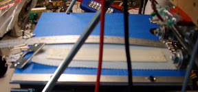
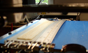
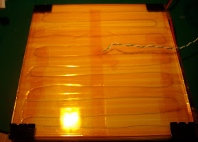
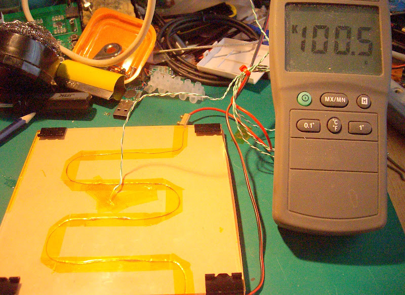
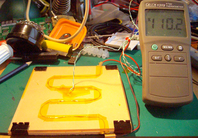
First problem was making the raft stick to Perspex eventually solved by fine tuning the first layer of the raft.

It must be slightly squashed but not so squashed that the extruder cant extrude.. and the filament kinks into a coil filling the space between the drive and the insulator.

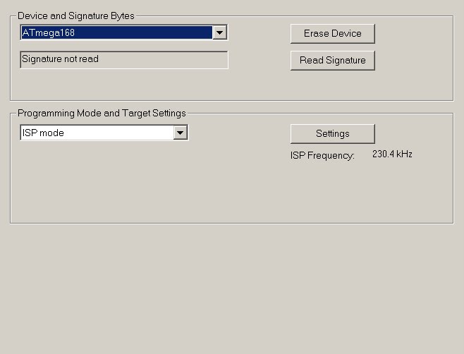
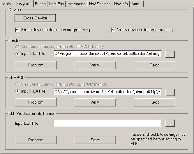
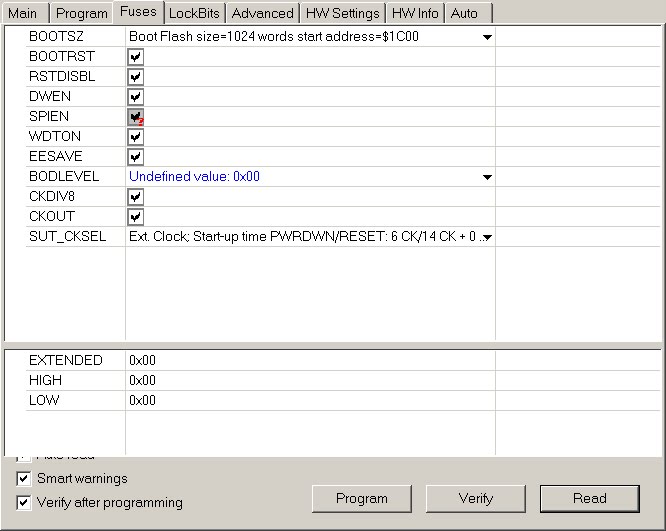
Next problem make sure you have the latest version of Repsnapper not the version pointed to by the RepRap WIKI the latest version is in the source in a directory called release. Though I'm not sure exactly what the difference is between the two windows version in the source other than they have slightly different UI interfaces.

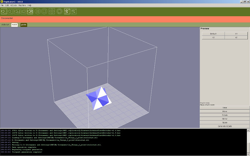
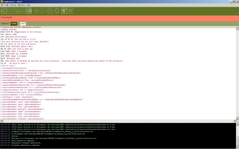
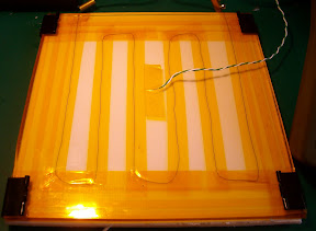
Next I found a bug in raft creation on Repsnapper its only shows if acceleration is not turned on. the second layer of raft creates G-code that has the E value missing for the middle section of the second layer the first 4 passes are OK then the middle section E values are missed out then the last 4 passes of the layer are OK.

G1 X102.59 Y94.0193 E82.5899 F2300
G1 X20 Y92.0193 E82.5899 F2300
G1 X102.59 Y90.0193 E82.5899 F2300
G1 X20 Y88.0193 E82.5899 F2300
G1 X102.59 Y86.0193 E82.5899 F2300
G1 X20 Y84.0193 E82.5899 F2300
G1 X102.59 Y82.0193 E82.5899 F2300
G1 X20 Y80.0193 E82.5899 F2300
G1 X102.59 Y78.0193 F2300
G1 X20 Y76.0193 F2300
G1 X102.59 Y74.0193 F2300
G1 X20 Y72.0193 F2300
G1 X102.59 Y70.0193 F2300
G1 X20 Y68.0193 F2300
G1 X102.59 Y66.0193 F2300
G1 X20 Y64.0193 F2300
G1 X102.59 Y62.0193 F2300
G1 X20 Y60.0193 F2300
G1 X102.59 Y58.0193 F2300
G1 X20 Y56.0193 F2300
G1 X102.59 Y54.0193 F2300
G1 X20 Y52.0193 F2300
G1 X102.59 Y50.0193 F2300
G1 X20 Y48.0193 F2300
G1 X102.59 Y46.0193 F2300
G1 X20 Y44.0193 F2300
G1 X102.59 Y42.0193 F2300
G1 X20 Y40.0193 F2300
G1 X102.59 Y38.0193 F2300
G1 X20 Y36.0193 F2300
G1 X102.59 Y34.0193 E82.5899 F2300
G1 X20 Y32.0193 E82.5899 F2300
G1 X102.59 Y30.0193 E82.5899 F2300
G1 X20 Y28.0193 E82.5899 F2300
G1 X102.59 Y26.0193 E82.5899 F2300
G1 X20 Y24.0193 E82.5899 F2300
G1 X102.59 Y22.0193 E82.5899 F2300
G1 X20 Y20.0193 E82.5899 F2300
G1 F70 ;Move Z
G1 Z3.3 F70 ;Move Z

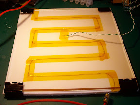
Switch acceleration on and its all fixed.. strange bug..
However the accelerated G-code also seems to have a very high number of feed rate setting G codes added that are identical.

G1 F2300
G1 X23 Y94.0193 E3 F2300
G1 X99.5899 Y94.0193 E76.5899 F2300
G1 X102.59 E3 F2300
G1 F2300
G1 X99.5899 Y92.0193 F2300
G1 X23 Y92.0193 E76.5899 F2300
G1 X20 E3 F2300
G1 F2300
G1 X23 Y90.0193 F2300
G1 X99.5899 Y90.0193 E76.5899 F2300
G1 X102.59 E3 F2300
G1 F2300
G1 X99.5899 Y88.0193 F2300
G1 X23 Y88.0193 E76.5899 F2300
G1 X20 E3 F2300
G1 F2300
G1 X23 Y86.0193 F2300
G1 X99.5899 Y86.0193 E76.5899 F2300
G1 X102.59 E3 F2300
G1 F2300
G1 X99.5899 Y84.0193 F2300
G1 X23 Y84.0193 E76.5899 F2300
G1 X20 E3 F2300
G1 F2300
G1 X23 Y82.0193 F2300
G1 X99.5899 Y82.0193 E76.5899 F2300
G1 X102.59 E3 F2300
G1 F2300
G1 X99.5899 Y80.0193 F2300
G1 X23 Y80.0193 E76.5899 F2300
G1 X20 E3 F2300
G1 F2300
G1 X23 Y78.0193 F2300
G1 X99.5899 Y78.0193 E76.5899 F2300
G1 X102.59 E3 F2300
G1 F2300
G1 X99.5899 Y76.0193 F2300
G1 X23 Y76.0193 E76.5899 F2300
G1 X20 E3 F2300
G1 F2300
G1 X23 Y74.0193 F2300
G1 X99.5899 Y74.0193 E76.5899 F2300
G1 X102.59 E3 F2300
G1 F2300
G1 X99.5899 Y72.0193 F2300
G1 X23 Y72.0193 E76.5899 F2300
G1 X20 E3 F2300
G1 F2300
G1 X23 Y70.0193 F2300
G1 X99.5899 Y70.0193 E76.5899 F2300
G1 X102.59 E3 F2300
G1 F2300
G1 X99.5899 Y68.0193 F2300
G1 X23 Y68.0193 E76.5899 F2300
G1 X20 E3 F2300
G1 F2300
G1 X23 Y66.0193 F2300
G1 X99.5899 Y66.0193 E76.5899 F2300
G1 X102.59 E3 F2300
G1 F2300
G1 X99.5899 Y64.0193 F2300
G1 X23 Y64.0193 E76.5899 F2300
G1 X20 E3 F2300
G1 F2300
G1 X23 Y62.0193 F2300
G1 X99.5899 Y62.0193 E76.5899 F2300
G1 X102.59 E3 F2300
G1 F2300
G1 X99.5899 Y60.0193 F2300
G1 X23 Y60.0193 E76.5899 F2300
G1 X20 E3 F2300
G1 F2300
G1 X23 Y58.0193 F2300
G1 X99.5899 Y58.0193 E76.5899 F2300
G1 X102.59 E3 F2300
G1 F2300
G1 X99.5899 Y56.0193 F2300
G1 X23 Y56.0193 E76.5899 F2300
G1 X20 E3 F2300
G1 F2300
G1 X23 Y54.0193 F2300
G1 X99.5899 Y54.0193 E76.5899 F2300
G1 X102.59 E3 F2300
G1 F2300
G1 X99.5899 Y52.0193 F2300
G1 X23 Y52.0193 E76.5899 F2300
G1 X20 E3 F2300
G1 F2300
G1 X23 Y50.0193 F2300
G1 X99.5899 Y50.0193 E76.5899 F2300
G1 X102.59 E3 F2300
G1 F2300
G1 X99.5899 Y48.0193 F2300
G1 X23 Y48.0193 E76.5899 F2300
G1 X20 E3 F2300
G1 F2300
G1 X23 Y46.0193 F2300
G1 X99.5899 Y46.0193 E76.5899 F2300
G1 X102.59 E3 F2300
G1 F2300
G1 X99.5899 Y44.0193 F2300
G1 X23 Y44.0193 E76.5899 F2300
G1 X20 E3 F2300
G1 F2300
G1 X23 Y42.0193 F2300
G1 X99.5899 Y42.0193 E76.5899 F2300
G1 X102.59 E3 F2300
G1 F2300
G1 X99.5899 Y40.0193 F2300
G1 X23 Y40.0193 E76.5899 F2300
G1 X20 E3 F2300
G1 F2300
G1 X23 Y38.0193 F2300
G1 X99.5899 Y38.0193 E76.5899 F2300
G1 X102.59 E3 F2300
G1 F2300
G1 X99.5899 Y36.0193 F2300
G1 X23 Y36.0193 E76.5899 F2300
G1 X20 E3 F2300
G1 F2300
G1 X23 Y34.0193 F2300
G1 X99.5899 Y34.0193 E76.5899 F2300
G1 X102.59 E3 F2300
G1 F2300
G1 X99.5899 Y32.0193 F2300
G1 X23 Y32.0193 E76.5899 F2300
G1 X20 E3 F2300
G1 F2300
G1 X23 Y30.0193 F2300
G1 X99.5899 Y30.0193 E76.5899 F2300
G1 X102.59 E3 F2300
G1 F2300
G1 X99.5899 Y28.0193 F2300
G1 X23 Y28.0193 E76.5899 F2300
G1 X20 E3 F2300
G1 F2300
G1 X23 Y26.0193 F2300
G1 X99.5899 Y26.0193 E76.5899 F2300
G1 X102.59 E3 F2300
G1 F2300
G1 X99.5899 Y24.0193 F2300
G1 X23 Y24.0193 E76.5899 F2300
G1 X20 E3 F2300
G1 F2300
G1 X23 Y22.0193 F2300
G1 X99.5899 Y22.0193 E76.5899 F2300
G1 X102.59 E3 F2300
G1 F2300
G1 X99.5899 Y20.0193 F2300
G1 X23 Y20.0193 E76.5899 F2300
G1 X20 E3 F2300
G1 F70 ;Move Z
G1 Z3.3 F70 ;Move Z

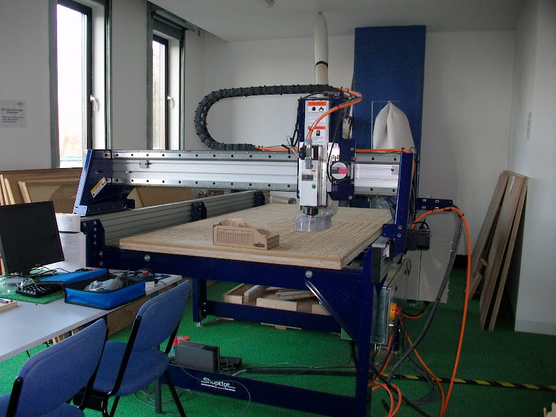
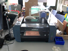
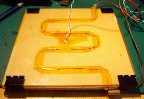
As my Rep strap Mendel was so loud I rebuilt all axis removing the skate bearings and using some linear bearings its much quieter now (i.e you cant hear it outside the Home Office)

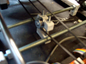
The next problem is Y belt jump/bounce I'm not sure if this is a common problem as I haven't seen it mentioned any where so It must be some thing peculiar to my set up.

I'm still using the original 80 thou" pitch belt bought from the RRRF ages ago. or 2.032mm pitch belt cut down to 4mm wide.

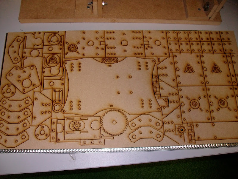
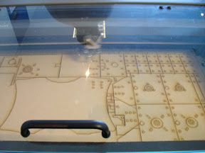
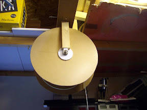
looking at a scanner that has a similar length of movement with a similar un-wired belt, I will try to simplify the rep strap Mendel drive to be more like the scanner drive belt system.

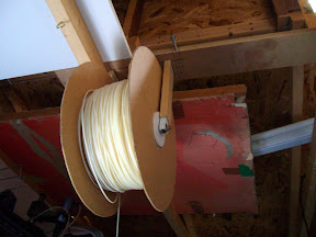
I do hope some one finds a neat way to re-cycle ABS waste as I have a growing collection building in a cardboard box now.

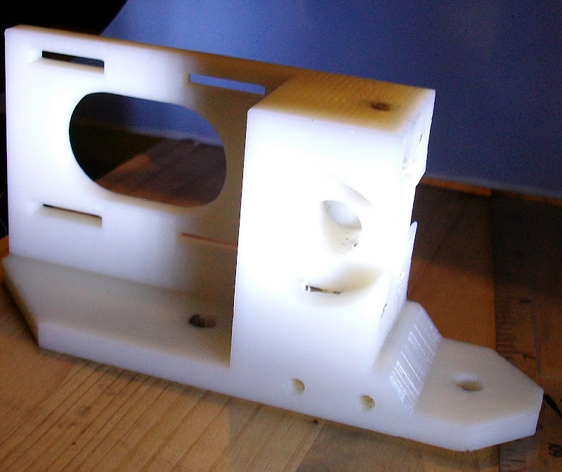
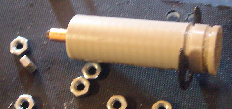
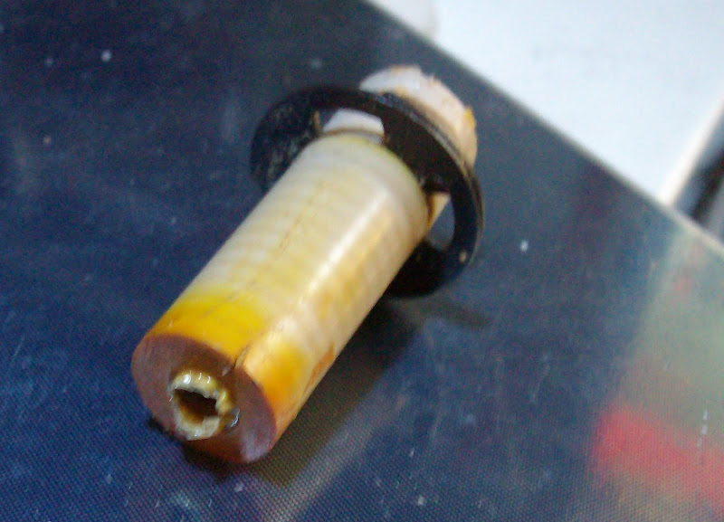
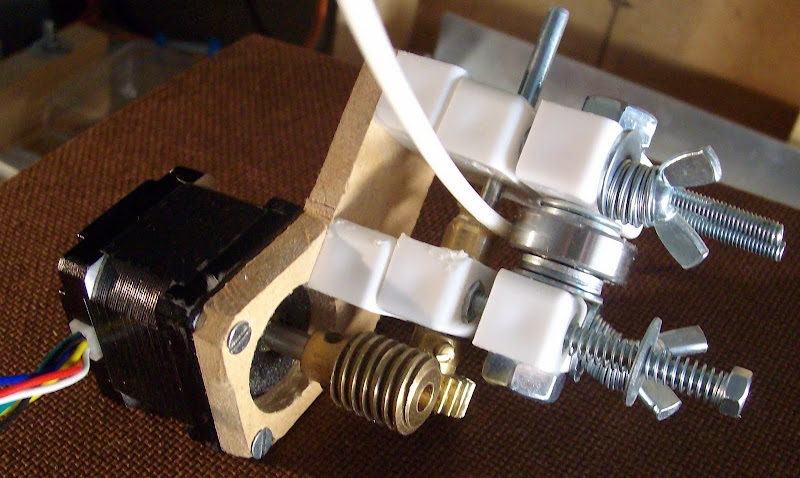
I'm very pleased with the performance of  my Mk5.5 Worm drive extruder that uses only 40mm of 16mm peek insulator with a 4.2mm hole through it and a 0.6mm welding tip with nichrome wire wraped around it. with a 4.2mm hole through it details and drawing I will post later.

Friday, October 8, 2010

Beginners luck.... ran out Warping warping nothing but warping...

Even though I had the Potbelly well stoked up and the temperature in the home office T shirt weather.

I fixed every thing that showed as a problem in the first print Tensioner for Y belt, filament reel etc.

Reel made from hardboard with £1 shop paint brush stand as the core covered in thick card 2 skate bearings 8mm threaded rod and two  22mm pipe clips drew around garden sieve to get sides. Tensioner two fix-it plastic blocks 2 springs 2 long 4mm screws 2 big washers 4 small washers 1 shorter 4mm screws 5 4mm nuts. 1 small bearing with 4mm hole.

I tried desperate measures to stop warping bigger rafts warming the print bed plate up on the Potbelly stove  before printing. So alas I must now find a way of using uninsulated Ni-chrome to heat the bed the other heated beds I made are all for Huxley / Mini Mendel so are too small.


As recomended by Kulitorum this is a RepRap Mendel Fan Mount from Thingyverse

The only explanation I can think of for the reasonable print of the Two spoons print is it has such a large overhang  i.e. it almost floats over the raft. That was why it did not warp.. just pure luck I saw it on the pipe when I was looking for my next test thing to try..

Next jobs Heated bed from what I have to hand without changing the structure of the existing almost working printer. Modifying the code to include a heated bed or using  a Pid controller with separate PSU... making a case to Suround the printer in case Midge opens the door to the cold out side. to prevent this I have waited till she is busy painting in the conservatory.

Thursday, October 7, 2010

Its been a good day for firsts.

Its been a good day for firsts.
The first fire in the Pot belly stove yea!!! and now Ta Da the first Repstrap Mendel print  using Bodgeits Extruder Mk5 Bodgeits modified version of Tonkip's 5D Gcode Interpreter firmware using Rep Snapper Host Software.

First here is a pic of the calibration prints or the eleven failed prints....


Failed due to things like extruder feed rate guesstimate was wrong, Z was too close to print, filament feed got stuck, X axis belt was slipping.
The only adjustment I need to do now is tighten the Y axis belt as it has a little slack that shows up when you watch the belt.

Then I can start to fine tune the speed and parameters in Rep-snapper.

So here is the clip of Rep Strap Mendel having a go at printing. 2 teaspoons // tablespoons at once!


Extruder details are as follows.

The extruder has an insulator of 16mm diameter 40mm long Peek with a 4.2mm hole through it with 6mm long 6mm thread hole to take a 6mm diameter 25mm long 0.6mm Welding tip.
The Welding tip is drilled out to 3.2mm for 24.2mm of its depth, leaving a 0.8mm long 0.6mm diameter hole to extrude thru.

6.8 ohms of Nichrome is wound onto the 25mm welding tip with a thermcouple and Kapton tape. Temprature measured using AD595A.

Plastic used ABS temprature was set to 255C

Wednesday, September 29, 2010

Quick update

The last September "Midge Ace Art studio open day" completed back to reprapping again..!

These were the Next Jobs:-

Get Pid or Bang Bang Extruder temprature control part working. Done
Get Pid or Bang Bang Build Base temprature control part working. Done

Make the drawings for Worm drive Extruder stepper.  Done (but took longer than expected!!)
.... drawings stepped up from Extruder MK3 to now Extruder Mk5 seems to be working very well so far.
I was able to hot swap ABS filament 

Make full size Mendel heated Bed with removable print surface as per WIKI . Done

Changes made to Mendel heated Bed 4mm Aluminum, extrude slot drilled out with 32mm drill, 6mm MDF insulation layer, Kapton tape electrical insulation layer nichrome wire heater element as used on my Huxley Fire glass heated bed in February.


Next Jobs
Firmware experiments to find best firmware combination/setup for RepSnapper to use with a single Arduino CPU configuration.

Then commit/post the final firmware as used on Bodgeits Git Hub repository.
Add pin config data and cct of FET drivers.

Make three more MK5 Worm drive Extruder steppers.
Re-build Repstrap Huxley1 adding precision ground slide bars with linear bearings.

Sunday, September 19, 2010

Connections for adding the Worm drive extruder stepper to Mendel.

V2.3 Stepper motor connections reminder sheet for Worm drive extruder stepper.

Pin Colour Name Function Motherboard V1.1
1 Brown N/C N/C
2 Red GND Ground. GND
3 Orange Step 500ns Step pulse Digital 10
4 Yellow Dir Set direction Digital 11
5 Green  !Enable Enable stepper Digital 14
6 Blue Min Min not used on Extruder
7 Violet Max Max not used on Extruder
8 Grey GND Ground.
9 White GND Ground.
10 Black GND Ground.


Connected and working using RepSnapper yay....

BodgeIts Next Jobs:-

Get Pid or Bang Bang Extruder temprature control part working.
Get Pid or Bang Bang Build Base temprature control part working.

Make the drawings for Worm drive Extruder stepper.
Make three more Worm drive Extruder steppers.
Re-build Repstrap Huxley1 adding presision ground slide bars with linear bearings.

Friday, September 17, 2010

BodgeIts Ardrino /Sanguino Motherboard 1.1 Pin / function crib table

Bodge It's Sanguino Motherboard 1.1 crib table dervied from this data on www.sanguino.cc and this circuit diagram on http://reprap.org/wiki/File:Cache-3316884519_b84b59fc90_b.jpg 

This is the resulting work table used to define BodgeIts pins in the FiveD Gcode Interpreter.

ATMega 644P ATMegag 644A


Chip Pin Chip Pin AtMega Name Arduino Name Function 1 Function 2 Function 3 Motherboard Use 1 REPRAP Use Bodgeits Use
1 40 PB-0 Digital 0 In/Out

Debug Led Debug Led Debug Led Digital 0
2 41 PB-1 Digital 1 In/Out


Digital 1
3 42 PB-2 Digital 2 In/Out INT 2
SD Card Write SD Card Write SD Card Write Digital 2
4 43 PB-3 Digital 3 In/Out PWM
SD Card Detect SD Card Detect SD Card Detect Digital 3
5 44 PB-4 Digital 4 In/Out PWM SS SD Card Select SD Card Select SD Card Select Digital 4
6 1 PB-5 Digital 5 In/Out MOS1
ICSP MOSI SD Card MOSI SD Card MOSI Digital 5
7 2 PB-6 Digital 6 In/Out MOS0
ICSP MISO SD Card MISO SD Card MISO Digital 6
8 3 PB-7 Digital 7 In/Out SCK
ICSP SCK SD Card SCK SD Card SCK Digital 7
14 9 PD-0 Digital 8 In/Out RX0
USB TTL RXD USB TTL RXD USB TTL RXD Digital 8
15 10 PD-1 Digital 9 In/Out TX0
USB TTL TXD USB TTL TXD USB TTL TXD Digital 9
16 11 PD-2 Digital 10 In/Out RX1 INT0 RS485 RXD RS485 RXD EXTRUDER_0_MOTOR_SPEED_PIN Digital 10
17 12 PD-3 Digital 11 In/Out TX1 INT1 RS485 TXD RS485 TXD EXTRUDER_0_MOTOR_DIR_PIN Digital 11
18 13 PD-4 Digital 12 In/Out PWM
RS485 TXE RS485 TXE EXTRUDER_0_HEATER_PIN Digital 12
19 14 PD-5 Digital 13 In/Out PWM
RS485 RXE RS485 RXE BASE_HEATER_PIN Digital 13
20 15 PD-6 Digital 14 In/Out PWM
PS_ON_Pin PS_ON_Pin EXTRUDER_0_STEP_ENABLE_PIN Digital 14
21 16 PD-7 Digital 15 In/Out PWM

X_Step_Pin X_Step_Pin Digital 15
22 19 PC-0 Digital 16 In/Out SCL
I2C SCL I2C SCL I2C SCL Digital 16
23 20 PC-1 Digital 17 In/Out SDA
I2C SDA I2C SDA I2C SDA Digital 17
24 21 PC-2 Digital 18 In/Out TCK
JTAG TCK X_Direction_Pin X_Direction_Pin Digital 18
25 22 PC-3 Digital 19 In/Out TMS
JTAG TMS X_Enable_Pin X_Enable_Pin Digital 19
26 23 PC-4 Digital 20 In/Out TD0
JTAG TD0 X_Min_Pin X_Min_Pin Digital 20
27 24 PC-5 Digital 21 In/Out TD1
JTAG TDI X_Max_Pin EXTRUDER_0_FAN_PIN Digital 21
28 25 PC-6 Digital 22 In/Out


Y_Direction_Pin Y_Direction_Pin Digital 22
29 26 PC-7 Digital 23 In/Out


Y_Step_Pin Y_Step_Pin Digital 23
33 37 PA-7 Digital 24 In/Out Analogue 7

Y_Enable_Pin Y_Enable_Pin Digital 24
34 36 PA-6 Digital 25 In/Out Analogue 6

Y_Min_Pin Y_Min_Pin Digital 25
35 35 PA-5 Digital 26 In/Out Analogue 5

Y_Max_Pin Bed Temp Digital 26
36 34 PA-4 Digital 27 In/Out Analogue 4

Z_Step_pin Z_Step_pin Digital 27
37 33 PA-3 Digital 28 In/Out Analogue 3

Z_Direction_pin Z_Direction_pin Digital 28
38 32 PA-2 Digital 29 In/Out Analogue 2

Z_Enable_Pin Z_Enable_Pin Digital 29
39 31 PA-1 Digital 30 In/Out Analogue 1

Z_Min_Pin Z_Min_Pin Digital 30
40 30 PA-0 Digital 31 In/Out Analogue 0

Z_Max_Pin EXTRUDER_0_TEMPERATURE_PIN Digital 31


9 4 RST


ICSP Reset JTAG Reset

10 6,18,38 VCC


ICSP VCC JTAG VCC

11 5,17,33 GND


ICSP GND JTAG GND

12 7 XTAL2


13 8 XTAL1


30 27 AVCC


31 28 GND


32 29 AREF


Thursday, September 16, 2010

BodgeIt is RepRapping in the Home Office at last!!

After a lot of playing around with Firmware and software I have decided to use the Repsnapper host software with a customized version of the 5D firmware. As I'm using a mixture of hardware on the various repstraps that I have.

So :-

RepstrapMendel is using Motherboard V1.1 with 4  2.3 stepper controllers the original PWM driver V1.1 board.

RepstrapHuxley1 is using Motherboard V1.1 with 3  2.3 stepper 1 Bodgeit micro Stepper & Vero FET Bd

RepstrapHuxley2 is using AudrinoMega with  4  1.2 stepper controllers & Vero FET switching board.

RepstrapDarwin1 is using AudrinoDemiglove with 4  1.2 stepper controller with a Vero FET switching board

RepstrapDarwin2  TBD (I need to make use of 4 extruder controllers that are currently redundant)


I made the two Huxley's way back in February this year when they would have been called mini Mendel's.
Once I finish the easier to make Mrk2 Huxley Strap I will post all the drawings in the WIKI if I learn to drive the WIKI input interface.

I have abandoned the MDF Makerbot build due to RS485 problems on V2.1 Extruder controllers.
I can now build the Makerbot firmware using my Ubunto10.04 machine (Thanks to several hours of work from Midge Ace  in exchange for setting up her Art studio & Conservatory then building her a 4.5m x 4.8m decking for the Cheshire Open Studios event last week and the weekend after next)

However my next most important job is to install the Potbelly stove in the home Office as its beginning to get a bit nippy at night in here.

Friday, August 6, 2010

Bodgeit has moved to into the Home Office at last. (short update)

Now the task of unpacking,  making the new space usable finding everything a nice home getting shelves storage units built ready to resume some RepRapping, computer is in place networked with printer on a recycled server rack and bench rescued from a trip to the tip. Finishing the Solar power installation next adding the backup server and Linux machines to run RepRap Mendel from.

Have been busy last week and this week with builders plumbers electrician and decorators who have replaced the conservatory floor, wiring, plumbing all wrecked by burst pipes at the beginning of the year while I was in hospital.. as the UK had the -18C big freeze.

Hence the lack of posts.

Monday, July 26, 2010

Makerbot RS485 ~ Extruder board: Null version reported! BUG mismatch ? ;-(

Having had a really Good experience with ReplicatorG18...
Generated a fair amount of Gcode to try on my MakerBot build..

I flashed my Sanguino / Mother Board V1.1 with the 1.6 version of the Makerbot SW.
works great until I try to run any steppers from my nice new Gcode. Boards light leds flash chips get warm motors stay stationary. Solution was edit the config file and change the line.

#define STEP_DELAY 175  // usual value is 1..?????

I cant think why I need to do this though usually this is delay is 1-2 uS

I came across this unwelcome error Message next when starting ReplicatorG you gt a Jar file mismatch warning on the rxtx lib and Dll. Visiting the site there is a warning saying this:-

"The 2.2pre2 bins contain the 2.2pre1 jar file and the 2.2pre2 native lib which causes a mismatch warning."

It is only a warning but playing it safe I installed the stable version


"Use newer binary version such as rxtx 2.1-7r2 (stable), which does work on Windows."

Next I then came across this problem of  "Extruder board: Null version reported!" going through over 85 threads in MakerBot Operators google group took some time as the threads were quite heavily replied to.

Provided little help as I have already tried every thing suggested to fix the problem.

Do any of you run the Makerbot firmware if so which hardware do you have brd versions.
I have two Motherboard V1.1 both work as Sanguino mother boards except maybe the RS485 interface is not working maybe... I have 4 built and working Extruder V2.1 extruder controllers all working except maybe the RS485 interface. Any Ideas on what I might be missing that is staring me in the face.


Firmware versions tried.
ASC 1.4,1.5,1.6,1.8HP,1.8 with SM 1.4,1.5 & 1.6
and the V2 Firmware MB-rrmbv12-V2 range used with the matching EC-ecv22-V2 range.
I have tried a little mixing and matching of versions but by no means all of the possible combinations.

Has any one else seen these problems??

1/. Having the need to increase the stepper delay by 175% to get steppers to work?
     Any ideas on what is going on why would my V2.3 Stepper boards or stepper motors need a longer step pulse to work? Nb I have seven working V2.3 stepper controller boards all fail with the 1-2uS delay.

2/. Is there a combination of Firmware that works if you have the V1.1 MB with V2.1 Extruder controllers?
   
     Both the MB and the EC boards work as Processors Controlling every thing else it only appears to be the R3485. I have used the latest boot loaders on both boards They flash every time with no problems.

From my look at the Hardware there is very little difference between the various versions of the MB and EC boards things like the reset switch ~ I rearranged the tracks to solve the PCB problem.

The whole set up is running from a 4A bench power supply max current hits 2A with all steppers running
Thus eliminating any switch mode noise as the PSUs are transformer type with internal CPU for voltage and current control.

Tuesday, July 20, 2010

Wey hey !!! The Beta 18 version of replicator G looks great Python selector works Great!

Wey Hey Cool very cool. Beta 18 version of replicator G!!
Almost a WFT apllication (Work First Time)


It is still not quite a work out of the Zip/box application as I still needed to add the Bat file to run it.
Special thanks to  doctoroctalpus at Makerbot for letting me know about the beta 18 version.

Screen shot with  stelocta4.stl from thingyverse loaded.


Gcode generated (Note this was just a my first play with ReplicatorG18) 


Here is the bat file I used.

@echo off

REM --- if you're running out of memory, change the 128m
REM --- (which means 128 megabytes) to something higher.

set SAVEDCP=%CLASSPATH%
set SAVEDPATH=%PATH%
set JAVA_HOME="C:\Program Files\java\bin"

if %JAVA_HOME% == "" GOTO Error

set CLASSPATH=java\lib\rt.jar;lib;lib\build;lib\vecmath.jar;lib\j3dcore.jar;lib\j3dutils.jar;lib\replicatorg.jar;lib\antlr.jar;lib\RXTXcomm.jar;lib\miglayout-3.7.jar;lib\oro.jar;lib\registry.jar;lib\mrj.jar
set PATH="C:\Program Files\python26";java\bin;java\lib;%PATH%

REM start javaw -ms128m -mx128m replicatorg.app.Base
%JAVA_HOME%\java replicatorg.app.Base

set CLASSPATH=%SAVEDCP%
set PATH=%SAVEDPATH%

GOTO End

:Error
echo *** Error: cannot execute ReplicatorG
echo *** Reason: lacking the directory where to find Java in your computer
echo ***
echo *** Fix: Edit run.bat and add the JAVA_HOME directory
echo *** at the 'set JAVA_HOME=""' line
echo ***
echo *** then call the batch file run.bat in order to execute ReplicatorG

:End
Pause
echo Bye.

Wednesday, July 7, 2010

The Home office is very nearly ready for moving in the Reprap Machines O'yea

With power connected to the Home Office. Im just waiting for this time next week to have the phone and internet connection connected so we can officaly move in.


So I have been gradualy catching up on whats been going on in the forums and on the fantastic Reprap aggregation pipe.

I saw this post from ReplicatorG I was completely impresed with the idea of its one stop shop approch with a single instaltaion of the the Software. How neat .. and it looks realy nice..


So I have downloaded it maybe three or four times as it has been revised from the original version through to version -R2.  Now I'm by no means a Java Guru of any kind I'm just an every day generic user of  applications using it. Applications like:-


The arduino-0012~arduino-0018, Python Open Office all run ok on my machine out of the Box so to speak.
But ReplicatorG would not until I recreated a start up batch file as was once used to sort out the environment variables with the start ReplicatorG batch file hey presto ReplicatorG now starts but fails when you try to run Skein forge as it won't recognize python! Grrrrr oh well got bored trying to figure out what the new environment variable problem is. I will have to come back to it later

Tuesday, April 20, 2010

Darwins and Mendels New home has risen off the ground

Not much to blog on Rep-rapping for quite some time.... I've had a few more PSVT attacks (4 this year) my last attack gave me my first trip with blue lights & siren in ambulace followed by some panic in resus.
After 3 lots of this stuff  where they thought It was a lot worse than it was. So with my Beat blocker dose now trebled I qualify for a fix...  Waiting for a consultation with the RF power enginner (consultant) for the lets burn out the extra wire in your heart with a bit of RF fix.

Any way back to Rep Rapping this will be the new home for Mendel, Darwin, two micro Mendels & Bodgeit to RepRap from with 3m high rafters to hang the plastic supply baskets from it should be fun.


The plans
http://bodgeitquicksolapowerdshed.blogspot.com/2010_01_24_archive.html


The Rep-Raping half is the West half the East half is the Artists studio for Midge.


What it looks like now
http://bodgeitquicksolapowerdshed.blogspot.com/2010_04_18_archive.html
 

Sunday, February 28, 2010

Rep strap Mini/Micro Mendel Heated Bed using Fire Glass

Building Mini or Micro Mendel for the show I don't know where I can get Aluminum sheet easily so I had an odd thought on Saturday when passing a Glass supplier so popped in to see if I could get some heat resistant glass 140mm x 138mm to use as a heated bed.


I was told I had to buy fire glass it can take up to 600C. I got lucky they had an off cut so I had two cut for £11 note this is good price as its usually £100 Square Meter. 


It has a slight yellow tint to it but as its not for looking through who cares.


Here are pictures of my attempts to get the element right using 50ohm per meter nichrome.


Note as I re-make them I start using much less Kapton tape  


The last attempt was the best achieving 100C in 6 minutes


Then 110C  in 7 minutes. I'm running from power supply no temperature control yet..


So resistance of final solution is about 20 ohms based on a 30.5 voltage and current of 1.5A total wattage is about 46 W. 


The original attempts were mounted on Plastic chopping board using bulldog type clips as the wattage went up the Plastic started to smoke so the final version has 3mm MDF bulldog-ed to the Fire Glass. I removed the two silver levers on each of the bull dog type clips.


I just need to figure out how to mount a Thermistor then I can add PID or Bang bang control of temprature using an extruder controller.


The nichrome has a 30mm spacing the other attempts were 10mm, 15mm, 20mm, 25mm to fit a 100mm x 100mm central print area.

Saturday, February 20, 2010

Unseen problems with buying SMT components.


Having just rung the Supplier as my last order had the wrong device supplied. I now find when taking pictures for my Micro Stepper to post on line here,  that the resistors supplied in my order at the beginning of the month are the wrong value.!!


Even with my 5 x magnifying head set on I could not read the value it wasn't till I snap a blog picture and crop it that I can see my 0.75 ohm resistors are actually 0.33 ohm.


So I now have one 74HC244 that's pretending to be AD595AQ chip that's been put on the rack or had 4 extra legs implanted.


I found this yesterday and went off shopping cross with my self for ordering a different type of Thermistor amp. It wasn't till the evening I got a magnifying glass out to see why I had ordered the wrong device.
That i saw it wasn't me but the device that was wrong. Ahhhhhhhh.


And now I find that 15 of my 0.75 ohm resistors are actually half  their former selves at 0.33 ohms..


What ever happened ISO 9002 or  BS5750 ?


Looks like I have a lost my Thermocouple test and now my  micro stepping weekend now !!


Dare I even try to use the 4 thermistors..?

I'm now just looking at the 4 glass thermistors that have no markings at all !! Except what was printed on the bag by the suppliers picking system which I now know is not that reliable!!. 

May be RS are not so expensive after all...


It takes quite a bit or me to be really irritated but this has just hit the Mark.. !!!

Thursday, February 18, 2010

KIcad the Etch a sketch for Grown Ups --Yay

My MicroMendel needs Microstepping so it was time to Play wit Ki-Cad


For a long while I have been looking for a nice PCB package as I want on occasion to make the odd board or two.


I have tried a few. KiCad so far is the only package that has not frustrated me beyond getting further than a day or so of messing around.
It gave me this nice result for a single sided micro stepper design that I can etch at home.


The only struggle I had and still have was creating a thermal pad so far I can create it.


I can see it but if I try to Print it the thermal pads vanish from my board design..


So I will stick some tape down where my thermal pads should be before I etch the board.


So if any of you know how to do thermal pads that will print for etching in Ki-Cad please please let me know.


Note you see them on your design absolutely great!! Try any combination of printing or plottingng saving to file they Vanish one of the Two bugs I found the other is in the electrical test thing in the cct / Schmatic drawing program I always have an error showing. Seems that its a random error as its different any time you try to change the part of-the error that is not there as it moves some where else.


Special thanks must go to AK47, Nophead and Grael in the Forums who all suggested Ki Cad very pleased !
I will be etching this board shortly.
Next job I now have is to take 4 CA-42 Nokia leads and turn them into 4 Serial leads for my controller boards thus saving well over $80 - $100 as I believe a serial lead is $20 US.
So just one serial cable for me would be $20 + Air freight cost  + £8 import handling + %17.5  VAT

Tuesday, February 9, 2010

4.7kg pull Extruder drive using Meccano Worm gear

Four Meccano worm gears arrived, that I dilled out to 4.5mm then 5mm to fit the stepper shaft.
I've removed the furniture screw, one plastic block thus reducing the flexing of the whole extruder assembly.
The 1st stepper I used was 4.6 kg/cm or  0.451  Nm torque it had no difficulty.
I'm now using a stepper with  4 times less torque at 1.1 kilogram centimeter or  0.108 newton meter. 

The geaing is 26:1 so the extruder resolution should be at least 20 times better than the splined shaft extruder. 

The drive has changed from 5mm splined shaft to 7mm gear drive.


Here is a picture of the new extruder.


Testing the New extruder causes my ABS stock hanging frame to start bending, as it goes past 4kg of pull.
I achieve 4.7kg of pull before the gripping pulley slips on the shaft or the gear slips on the shaft or on the ABS rod. I.E. tighten the gear the shaft slips with the pulley tighten the pulley the gear slips or the ABS then slips. The Conrad gear or an AK47 "worm" gear are just about the same as each other in my set up no difference.. my  "worm" may not be as good as it should thou!


I need flats on the shaft and stronger springs to clamp the bearing into a sharper "worm" pulley.


If the splined shaft gave me 1.7 kg pull this must be not far off Adrian's pukka Mendel extruder.
Getting 4.7kg pull with a low cost low torque stepper using an easy to make drive construction.
Is the best I can do so I'm giving up trying to get a better pull than  4.7kg for now.
My next task is to add a feed guide then  marry the extruder to the drive system test then add it to Mendel.


As I need to have two working machines for the show time is short for me to mess around any more trying to get better results that may not be needed. There is still the PID temprature control to get working for both the Ext ruder and Bed yet. I will make drawings once I can prove it works OK if there is time left before the show to do that.


Oh the side effect of the smaller stepper is the whole assembly has weight reduction from 560gms down to 346gms. Just over 200gm weight saving if that will make any difference to performance... ??? I don't know ???
  
I think I have achieved the best pull I can with out using any RepRapped or specially machined parts.

Bodgits definitive guide to Flashing Boot loaders Using AVR Studio


I am blogging this mainly for my own reference as you generally do not Flash boot Loaders often. As I had to re-learn the whole process again As I had five bootloaders to load.


Previously I grabbed the AVR data sheet to figure out the settings required fuses and lock bits.


This time I found it was easier to use the information stored here:-


X:\Program Files\arduino-0017\hardware\boards.txt


This file is found on any PC that has the Arduino Software installed.


The boards.txt file will look like my slightly modified Boards.txt file:-

##############################################################

extruder1p.name=Extruder1p
extruder1p.upload.protocol=stk500
extruder1p.upload.maximum_size=63488
extruder1p.upload.speed=38400
extruder1p.bootloader.low_fuses=0xFF
extruder1p.bootloader.high_fuses=0xDC
extruder1p.bootloader.extended_fuses=0xFD
extruder1p.bootloader.path=atmega644p
extruder1p.bootloader.file=ATmegaBOOT_644.hex
extruder1p.bootloader.unlock_bits=0x3F
extruder1p.bootloader.lock_bits=0x0F                << note reads as CF in AVR studio so needs to be 0xCF.
extruder1p.build.mcu=atmega644p
extruder1p.build.f_cpu=16000000L
extruder1p.build.core=sanguino
extruder1p.verbose=false

##############################################################

extruder1.name=Extruder1
extruder1.upload.protocol=stk500
extruder1.upload.maximum_size=63488
extruder1.upload.speed=38400
extruder1.bootloader.low_fuses=0xFF
extruder1.bootloader.high_fuses=0xDC
extruder1.bootloader.extended_fuses=0xFD
extruder1.bootloader.path=atmega644p
extruder1.bootloader.file=ATmegaBOOT_644.hex
extruder1.bootloader.unlock_bits=0x3F
extruder1.bootloader.lock_bits=0x0F                << note reads as CF in AVR studio so needs to be 0xCF.
extruder1.build.mcu=atmega644
extruder1.build.f_cpu=16000000L
extruder1.build.core=sanguino
extruder1.verbose=false

##############################################################

motherboard.name=Motherboard
motherboard.upload.protocol=stk500
motherboard.upload.maximum_size=63488
motherboard.upload.speed=38400
motherboard.bootloader.low_fuses=0xFF
motherboard.bootloader.high_fuses=0xDC
motherboard.bootloader.extended_fuses=0xFD
motherboard.bootloader.path=atmega644p
motherboard.bootloader.file=ATmegaBOOT_644.hex
motherboard.bootloader.unlock_bits=0x3F
motherboard.bootloader.lock_bits=0x0F                << note reads as CF in AVR studio so needs to be 0xCF.
motherboard.build.mcu=atmega644
motherboard.build.f_cpu=16000000L
motherboard.build.core=sanguino
motherboard.verbose=false

##############################################################

sanguino.name=Sanguino
sanguino.upload.protocol=stk500
sanguino.upload.maximum_size=63488
sanguino.upload.speed=38400
sanguino.bootloader.low_fuses=0xFF
sanguino.bootloader.high_fuses=0xDC
sanguino.bootloader.extended_fuses=0xFD
sanguino.bootloader.path=atmega644p
sanguino.bootloader.file=ATmegaBOOT_644P.hex
sanguino.bootloader.unlock_bits=0x3F
sanguino.bootloader.lock_bits=0x0F                 << note reads as CF in AVR studio so needs to be 0xCF.
sanguino.build.mcu=atmega644p
sanguino.build.f_cpu=16000000L
sanguino.build.core=sanguino
sanguino.verbose=false

~~~~~~~~~~~~~~~~~~~~~~~~~~~~~~~~~~~~~~~~~~~~~~~~~~~~~~~~~~~~~~~~~~~~~

This file is a lot longer I am just showing the board details for Extruder1.1, Motherboard1.1 and Sanguino1.1

The Single Sided Audrion board I made here 
Is shown above after drilling I ironed on the component outline image to make it easier to build. 
My first misshap on testing the boards was one Extruder controller fried a processor due to a bad V regulator that didnt regulate. Cut the Atmega off using a craft knife in a scoring motion accross the pins.
De solderd the offending regulator. 


Misshap number two one of the pads for the CPU lifted off in fact typical one of the few that has its connection under the chip.. located the via hole solderd a wire on to the pin BIG mistake should have solderd the via hole end first. as the pin broke off at the plastic to pin join. night mare !! fixed with steady hand and a drop of araldite to prevent any further miss haps.


So 1 Extruder board now has a 168P the others have 168 CPUs.


 Back to Flashing bootloaders using AVR studio connecte a board to your programer select the chip icon with AVR on it its a mid screen


Select read Signature and correct the device name if nesasary and re-read to double check.


You may now select the program Tab in the Flash section you can select the boot loader file you want on the device and then select the Program button. You now select the Fuses Tab.


Now using the Settings found in the file Boards.txt for the Extended High and low fuses. Correct the settings by typing in the values for Extended High and low fuses from the file then select program.


Example from flashing the Motherboard 1.1 chip.


Now select the Lock bits. All you need is the option that locks the boot section from being writen to.


Job Done!!


Please note that some of the Lock bits in the files should be 0xCF not 0x0F the fuse values are read as high for any non existent bits by AVR studio in the boards.txt file they are show as not there. I have adjusted these to be correct for AVR studio in my Boards.txt file.