Sunday, February 28, 2010

Rep strap Mini/Micro Mendel Heated Bed using Fire Glass

Building Mini or Micro Mendel for the show I don't know where I can get Aluminum sheet easily so I had an odd thought on Saturday when passing a Glass supplier so popped in to see if I could get some heat resistant glass 140mm x 138mm to use as a heated bed.


I was told I had to buy fire glass it can take up to 600C. I got lucky they had an off cut so I had two cut for £11 note this is good price as its usually £100 Square Meter. 


It has a slight yellow tint to it but as its not for looking through who cares.


Here are pictures of my attempts to get the element right using 50ohm per meter nichrome.


Note as I re-make them I start using much less Kapton tape  


The last attempt was the best achieving 100C in 6 minutes


Then 110C  in 7 minutes. I'm running from power supply no temperature control yet..


So resistance of final solution is about 20 ohms based on a 30.5 voltage and current of 1.5A total wattage is about 46 W. 


The original attempts were mounted on Plastic chopping board using bulldog type clips as the wattage went up the Plastic started to smoke so the final version has 3mm MDF bulldog-ed to the Fire Glass. I removed the two silver levers on each of the bull dog type clips.


I just need to figure out how to mount a Thermistor then I can add PID or Bang bang control of temprature using an extruder controller.


The nichrome has a 30mm spacing the other attempts were 10mm, 15mm, 20mm, 25mm to fit a 100mm x 100mm central print area.

Saturday, February 20, 2010

Unseen problems with buying SMT components.


Having just rung the Supplier as my last order had the wrong device supplied. I now find when taking pictures for my Micro Stepper to post on line here,  that the resistors supplied in my order at the beginning of the month are the wrong value.!!


Even with my 5 x magnifying head set on I could not read the value it wasn't till I snap a blog picture and crop it that I can see my 0.75 ohm resistors are actually 0.33 ohm.


So I now have one 74HC244 that's pretending to be AD595AQ chip that's been put on the rack or had 4 extra legs implanted.


I found this yesterday and went off shopping cross with my self for ordering a different type of Thermistor amp. It wasn't till the evening I got a magnifying glass out to see why I had ordered the wrong device.
That i saw it wasn't me but the device that was wrong. Ahhhhhhhh.


And now I find that 15 of my 0.75 ohm resistors are actually half  their former selves at 0.33 ohms..


What ever happened ISO 9002 or  BS5750 ?


Looks like I have a lost my Thermocouple test and now my  micro stepping weekend now !!


Dare I even try to use the 4 thermistors..?

I'm now just looking at the 4 glass thermistors that have no markings at all !! Except what was printed on the bag by the suppliers picking system which I now know is not that reliable!!. 

May be RS are not so expensive after all...


It takes quite a bit or me to be really irritated but this has just hit the Mark.. !!!

Thursday, February 18, 2010

KIcad the Etch a sketch for Grown Ups --Yay

My MicroMendel needs Microstepping so it was time to Play wit Ki-Cad


For a long while I have been looking for a nice PCB package as I want on occasion to make the odd board or two.


I have tried a few. KiCad so far is the only package that has not frustrated me beyond getting further than a day or so of messing around.
It gave me this nice result for a single sided micro stepper design that I can etch at home.


The only struggle I had and still have was creating a thermal pad so far I can create it.


I can see it but if I try to Print it the thermal pads vanish from my board design..


So I will stick some tape down where my thermal pads should be before I etch the board.


So if any of you know how to do thermal pads that will print for etching in Ki-Cad please please let me know.


Note you see them on your design absolutely great!! Try any combination of printing or plottingng saving to file they Vanish one of the Two bugs I found the other is in the electrical test thing in the cct / Schmatic drawing program I always have an error showing. Seems that its a random error as its different any time you try to change the part of-the error that is not there as it moves some where else.


Special thanks must go to AK47, Nophead and Grael in the Forums who all suggested Ki Cad very pleased !
I will be etching this board shortly.
Next job I now have is to take 4 CA-42 Nokia leads and turn them into 4 Serial leads for my controller boards thus saving well over $80 - $100 as I believe a serial lead is $20 US.
So just one serial cable for me would be $20 + Air freight cost  + £8 import handling + %17.5  VAT

Tuesday, February 9, 2010

4.7kg pull Extruder drive using Meccano Worm gear

Four Meccano worm gears arrived, that I dilled out to 4.5mm then 5mm to fit the stepper shaft.
I've removed the furniture screw, one plastic block thus reducing the flexing of the whole extruder assembly.
The 1st stepper I used was 4.6 kg/cm or  0.451  Nm torque it had no difficulty.
I'm now using a stepper with  4 times less torque at 1.1 kilogram centimeter or  0.108 newton meter. 

The geaing is 26:1 so the extruder resolution should be at least 20 times better than the splined shaft extruder. 

The drive has changed from 5mm splined shaft to 7mm gear drive.


Here is a picture of the new extruder.


Testing the New extruder causes my ABS stock hanging frame to start bending, as it goes past 4kg of pull.
I achieve 4.7kg of pull before the gripping pulley slips on the shaft or the gear slips on the shaft or on the ABS rod. I.E. tighten the gear the shaft slips with the pulley tighten the pulley the gear slips or the ABS then slips. The Conrad gear or an AK47 "worm" gear are just about the same as each other in my set up no difference.. my  "worm" may not be as good as it should thou!


I need flats on the shaft and stronger springs to clamp the bearing into a sharper "worm" pulley.


If the splined shaft gave me 1.7 kg pull this must be not far off Adrian's pukka Mendel extruder.
Getting 4.7kg pull with a low cost low torque stepper using an easy to make drive construction.
Is the best I can do so I'm giving up trying to get a better pull than  4.7kg for now.
My next task is to add a feed guide then  marry the extruder to the drive system test then add it to Mendel.


As I need to have two working machines for the show time is short for me to mess around any more trying to get better results that may not be needed. There is still the PID temprature control to get working for both the Ext ruder and Bed yet. I will make drawings once I can prove it works OK if there is time left before the show to do that.


Oh the side effect of the smaller stepper is the whole assembly has weight reduction from 560gms down to 346gms. Just over 200gm weight saving if that will make any difference to performance... ??? I don't know ???
  
I think I have achieved the best pull I can with out using any RepRapped or specially machined parts.

Bodgits definitive guide to Flashing Boot loaders Using AVR Studio


I am blogging this mainly for my own reference as you generally do not Flash boot Loaders often. As I had to re-learn the whole process again As I had five bootloaders to load.


Previously I grabbed the AVR data sheet to figure out the settings required fuses and lock bits.


This time I found it was easier to use the information stored here:-


X:\Program Files\arduino-0017\hardware\boards.txt


This file is found on any PC that has the Arduino Software installed.


The boards.txt file will look like my slightly modified Boards.txt file:-

##############################################################

extruder1p.name=Extruder1p
extruder1p.upload.protocol=stk500
extruder1p.upload.maximum_size=63488
extruder1p.upload.speed=38400
extruder1p.bootloader.low_fuses=0xFF
extruder1p.bootloader.high_fuses=0xDC
extruder1p.bootloader.extended_fuses=0xFD
extruder1p.bootloader.path=atmega644p
extruder1p.bootloader.file=ATmegaBOOT_644.hex
extruder1p.bootloader.unlock_bits=0x3F
extruder1p.bootloader.lock_bits=0x0F                << note reads as CF in AVR studio so needs to be 0xCF.
extruder1p.build.mcu=atmega644p
extruder1p.build.f_cpu=16000000L
extruder1p.build.core=sanguino
extruder1p.verbose=false

##############################################################

extruder1.name=Extruder1
extruder1.upload.protocol=stk500
extruder1.upload.maximum_size=63488
extruder1.upload.speed=38400
extruder1.bootloader.low_fuses=0xFF
extruder1.bootloader.high_fuses=0xDC
extruder1.bootloader.extended_fuses=0xFD
extruder1.bootloader.path=atmega644p
extruder1.bootloader.file=ATmegaBOOT_644.hex
extruder1.bootloader.unlock_bits=0x3F
extruder1.bootloader.lock_bits=0x0F                << note reads as CF in AVR studio so needs to be 0xCF.
extruder1.build.mcu=atmega644
extruder1.build.f_cpu=16000000L
extruder1.build.core=sanguino
extruder1.verbose=false

##############################################################

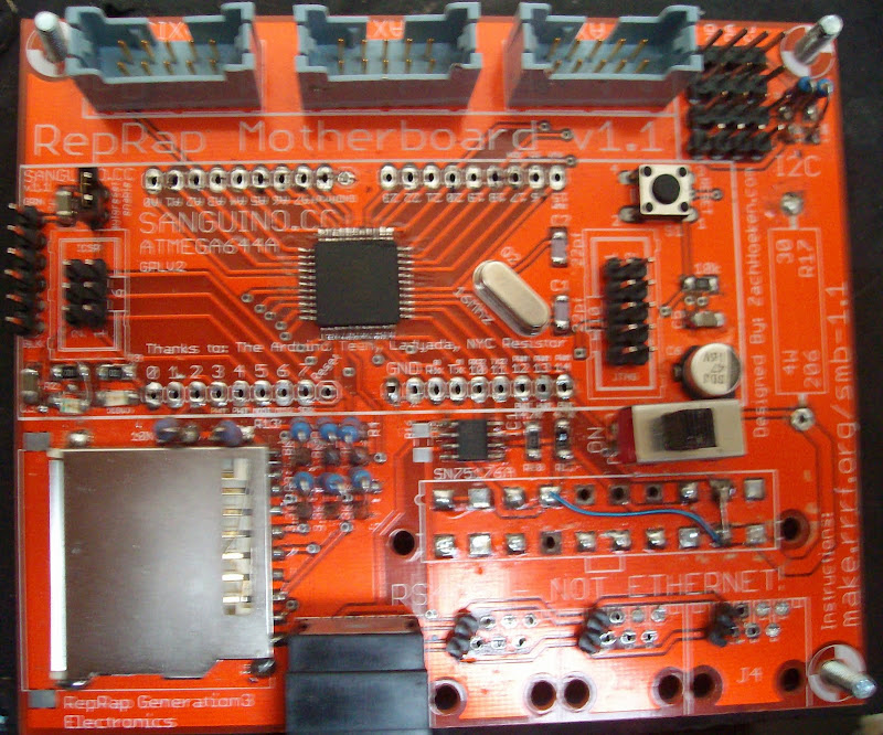
motherboard.name=Motherboard
motherboard.upload.protocol=stk500
motherboard.upload.maximum_size=63488
motherboard.upload.speed=38400
motherboard.bootloader.low_fuses=0xFF
motherboard.bootloader.high_fuses=0xDC
motherboard.bootloader.extended_fuses=0xFD
motherboard.bootloader.path=atmega644p
motherboard.bootloader.file=ATmegaBOOT_644.hex
motherboard.bootloader.unlock_bits=0x3F
motherboard.bootloader.lock_bits=0x0F                << note reads as CF in AVR studio so needs to be 0xCF.
motherboard.build.mcu=atmega644
motherboard.build.f_cpu=16000000L
motherboard.build.core=sanguino
motherboard.verbose=false

##############################################################

sanguino.name=Sanguino
sanguino.upload.protocol=stk500
sanguino.upload.maximum_size=63488
sanguino.upload.speed=38400
sanguino.bootloader.low_fuses=0xFF
sanguino.bootloader.high_fuses=0xDC
sanguino.bootloader.extended_fuses=0xFD
sanguino.bootloader.path=atmega644p
sanguino.bootloader.file=ATmegaBOOT_644P.hex
sanguino.bootloader.unlock_bits=0x3F
sanguino.bootloader.lock_bits=0x0F                 << note reads as CF in AVR studio so needs to be 0xCF.
sanguino.build.mcu=atmega644p
sanguino.build.f_cpu=16000000L
sanguino.build.core=sanguino
sanguino.verbose=false

~~~~~~~~~~~~~~~~~~~~~~~~~~~~~~~~~~~~~~~~~~~~~~~~~~~~~~~~~~~~~~~~~~~~~

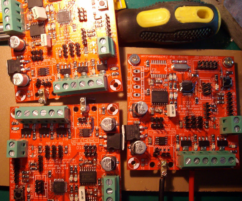
This file is a lot longer I am just showing the board details for Extruder1.1, Motherboard1.1 and Sanguino1.1

The Single Sided Audrion board I made here 
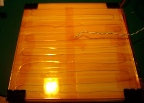
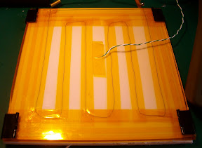
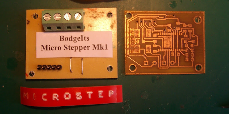
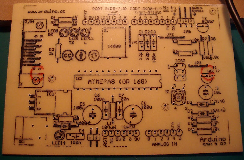
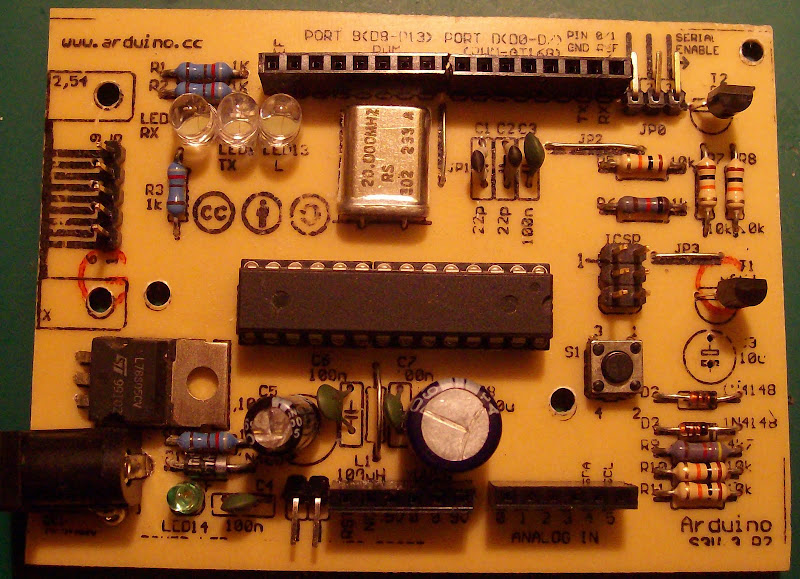
Is shown above after drilling I ironed on the component outline image to make it easier to build. 
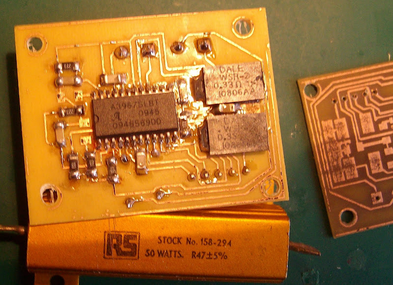
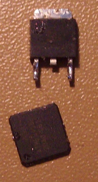
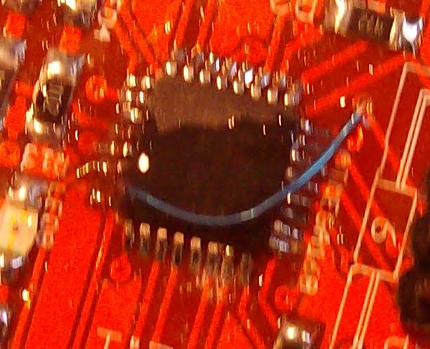
My first misshap on testing the boards was one Extruder controller fried a processor due to a bad V regulator that didnt regulate. Cut the Atmega off using a craft knife in a scoring motion accross the pins.
De solderd the offending regulator. 


Misshap number two one of the pads for the CPU lifted off in fact typical one of the few that has its connection under the chip.. located the via hole solderd a wire on to the pin BIG mistake should have solderd the via hole end first. as the pin broke off at the plastic to pin join. night mare !! fixed with steady hand and a drop of araldite to prevent any further miss haps.


So 1 Extruder board now has a 168P the others have 168 CPUs.


 Back to Flashing bootloaders using AVR studio connecte a board to your programer select the chip icon with AVR on it its a mid screen


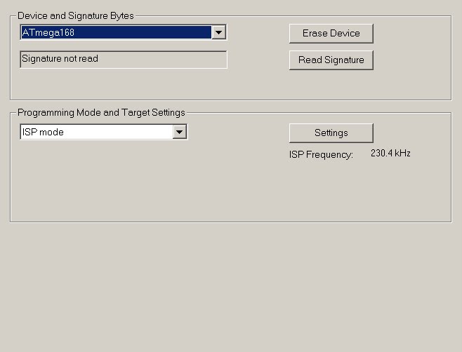
Select read Signature and correct the device name if nesasary and re-read to double check.


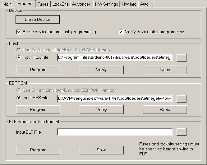
You may now select the program Tab in the Flash section you can select the boot loader file you want on the device and then select the Program button. You now select the Fuses Tab.


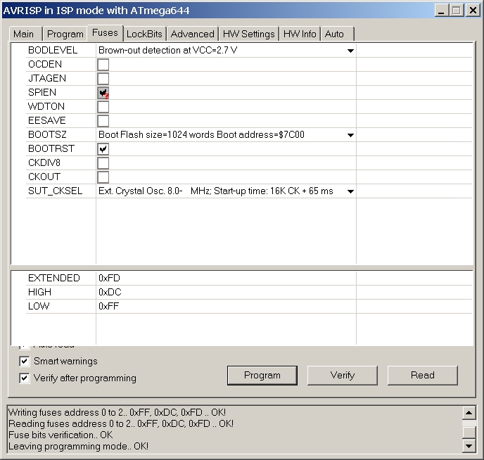
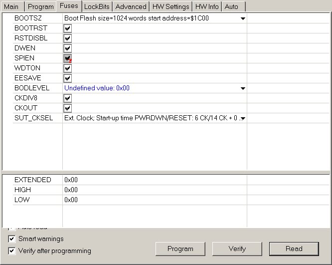
Now using the Settings found in the file Boards.txt for the Extended High and low fuses. Correct the settings by typing in the values for Extended High and low fuses from the file then select program.


Example from flashing the Motherboard 1.1 chip.


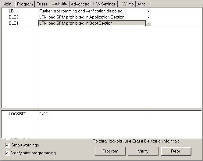
Now select the Lock bits. All you need is the option that locks the boot section from being writen to.


Job Done!!


Please note that some of the Lock bits in the files should be 0xCF not 0x0F the fuse values are read as high for any non existent bits by AVR studio in the boards.txt file they are show as not there. I have adjusted these to be correct for AVR studio in my Boards.txt file.


Monday, February 1, 2010

CALL FOR ALL REPRAPPERS – MAKER FAIRE 2010 IN NEWCASTLE, UK


CALL FOR ALL REPRAPPERS – MAKER FAIRE 2010 IN NEWCASTLE, UK


Great news for all us Reprappers! I have been lucky enough to be allocated a stand at MAKER FAIRE 2010 in Newcastle, UK. This is the second one to be held here following its success in 2009 which had a great response and caught the attention of the BBC!

I have been initially allocated a 3x3m slot but can request more space if needed. It will have internet connection which will be useful to hook up to other colleagues around the world during the show if necessary. I have until 8th February to submit my requirements for the show.

Throughout the two days (i.e. 13th and 14th March) I will also be able to hold 30 minute demonstrations on how it works and source of suppliers.

At the moment I am just buzzing with the news as I know from previous experience doing computer fair shows how much can be gained. This kind of thing attracts lots of publicity such as the BBC etc. Thus I believe this could be a brilliant opportunity for us RepRappers to promote the project further in the UK and presumably as a result also worldwide!

Maybe this is also a good way for us Reprappers in the UK to get together? … make it a yearly meet up? What do you think?

Current Ideas

Last year someone 3D-printed ornaments. Personally I would like to do something a bit more spectacular to capture everyone’s imagination.

Duy Nguyen had a good suggestion of people printing specific parts and mailing them to one location to be assembled into something … I think this would be good if Reprappers around the world could print a specific Reprap part, send it to the show and then it is assembled into a Reprap machine.

The only thing I don’t know is if there are enough of us out there that can actually print all the actual parts in time for the show? 

I also liked Gene Hacker’s suggestion of “Teleporting” objects as it was what I also had in mind. Maybe the Reprap assembled at the show can demonstrate how it works by printing something sent from another country or replicating one of its parts?

So what I am looking for at the moment is:

a)     To hear from Reprapper’s that can actually print Reprap parts
b)     Volunteers, ideas and suggestions for the “Teleport” demonstration
c)     Submission of Videos, images, artwork etc that can be displayed during the show e.g. could be of those printing the reprap parts for the show! Or other related interesting things? … open to suggestions but remember only 30 minutes allowed for video demos!
d)     Any UK Reprapper’s that have a machine they would like to bring and demonstrate at the show or those that would like to accompany us to or meet us at the show?
e)     We will need to have between 6-8 people+ on the stand at the show so any volunteers to help out would be greatly welcomed.
f)      As much help and support to make this opportunity a big success!

Please note the stand is strictly not commercial so no offers to sell products please. However, I am not sure, but will find out if promotional material can be displayed on the stand which I will be happy to do.

It would be really good if some of the members of the UK Core Team could attend!!!

Deadline for suggestions, volunteers, demonstrators and participants that are interested is 5th February 2010 as I will need time to collate everything and contact everyone to make arrangements prior to my requirements submission on 8th February.

So RepRappers get your thinking caps on and post your comments to the
CALL FOR ALL REPRAPPERS – MAKER FAIRE 2010 IN NEWCASTLE, UK
thread on our forum under General discussions.