
Some times some thing is stareing you in the face and yet you dont see it.
Well after two weeks I have seen it by taking just a few 5mm spring washers and 6mm spring washers. I have reduced the number of skate bearings required from 32 down to 24 skate bearings a significant saveing.
You could save 4 more by keeping the 3 and 2 bearing configuration of Mendel.
Im lazy and it was easier to just change 1 block per boggie thus mine are all 3 bearing blocks now. Maybe once its all going I will change the Y axis to be a 3 and a 2 configuration.

Here is the method to make both types the three and the two bearing types.
Three bearing boggies.
Here is how you assemble one:
1 nylon corner block in this order.
1 8mm bolt 1 bearing, 1 nut, 1 bearing, 1 washer, Nylon corner block and a nut.
Using two 4mm screw put thru the two holes of 2 bearing block then put an un modified block on the two screws first block now add two 5mm spring washers on to the 4mm screws then add the next block thats made in this order:
1 bearing, 1 nut, 1 washer, Nylon corner block and a nut.
Add the two nuts to hold the new bogie assembly together.
Two bearing boggies.
Here is how you assemble one:
Make 2 nylon corner block in this order.
1 bearing, 1 nut, 1 washer, Nylon corner block and a nut.
Using two 4mm screw put thru the two holes of 1 bearing block now add two 6mm flat washers on to the 4mm screws then put an un modified block on the two screws then two 6mm flat washers folowed by the second 1 bearing block
Add the two nuts to hold the new bogie assembly together.

The 3 bearing seperation is based on the 5mm spring washers bein 1.3mm - 1.4mm when comppresed spring washers are better as it gives you the ability to loosen or tighten the grip of the skate bearings.
The 2 bearing seperation is based on the 6mm spring washers bein 1.4mm - 2mm when comppresed spring washers are better as it gives you the ability to loosen or tighten the grip of the skate bearings.
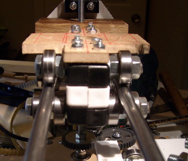
New image uploaded for oiaohm to show how the bevel on the skate bearings works to produce the effect of 3 bearings at 120 degrees this effect definatly provides a slider with much less friction than using the four bearings boggies. I do not know the angle of the bevel maybe it is a 60 degree bevel.

12 comments:
I did wonder about that one, after watching the Mendel video, the 3 + 2 bearing system seems so obvious, but I have made a bearing bogie like yours and it works so well and seems so right that I just thought you were going with it anyway.
Your previous comment about gear backlash on the Z axis has got me thinking too! You said that the Z axis only needs to go one way so backlash isnt really an issue. How true, and it got me thinking about the whole multiple threaded rod issue. If we use a series of tapering ramps under the z axis and push them forwards and backwards with a threaded rod, we can move the whole z axis with just one threaded rod. This isnt much help with a Mendel type reprap/repstrap but my CopperRap 2 will certainly benefit from this approach.
Just about to start some bogeying!
Hey yes not sure what you mean by a series of taperd ramps as I think just two ramps from MDF would work with a thin strip of plastic on top as a sliding surface.. Or you could use 8mm bar for the ramps with bearings on the x axis assembly they would have to match the rake of the ramp thou. the extra bits might negate saving £10-£12 on the cost of a stepper motor tho.
The diffrence from 4 bearings to 3 is very noticeable it seems to run much smoother. I will apply the Boggie change to my darwin builds. I am nearly finished with Mendel now I had to rush it a bit to clear the Kitchen for Christmass I'm just making a base for Mendel so it will become like a portable sewing machine. Been typing he Blog as I go but not published it yet my batteries died in my camera. So making the stepper controllers at the moment. While the paint dries on the base board. Due to snow and ice the shed build has stalled..
It may be possible to reduce the bearing numbers further if you make a tyre that goes on the outer race and has a channel around it.
Admitedly this could be dificult without a strap machine unless you had a lathe or used a pillar drill as a lathe.
Just some quick thoughts.
Im thinking that three or four ramps, basically one in each corner. I can restriain the position of the bed so that it can only move in the Z direction, then have a duplicate bed below, but inverted. The single stepper will pull the inverted bed and the two sets of ramps will slide against each other and raise the bed.
Its not really the cost of a stepper Im trying to save, its to prevent the multiple threaded rods binding and removing the need for a long continuos belt.
Im intrigued by your comments regarding smoothness, I must give it a go!
Ok so close but so far. Don't use the sides of bearing full stop. Sides of bearings surface travels at slightly different speeds and those differences cause friction.
Use the out edge only. The lowest friction but held is 3 bearing mounted around one shaft on one side and 2 on the other.
But the 3 bearing must have the out of edge pointing perfectly at the running shaft to work. Basically 120 degrees apart in angle to each other.
Next best is a 4 setup. The 4 are very much just a double set of 2 like for the second track. One set of two vertically as normal and one set horizontally to keep it on the track. 2 set of 4 would have to be fitted. Normally. horizon guides outside the vertical load bearing.
Yes I know this will not reduce bearings. 12 is per carage kinda the magic number for least friction and simplest construction. To go less than 12 you need to be able to do 3 directional guides. Raprep printer should be able to produce those holders.
There is another 3 all around that you have to be careful of. 2 bearing vertically 1 horizontal pointing out. Has a bad habit of splitting the tracks over time until they are too far apart and bad things happen.
Seams like a good idea to cut a grove in a tire around a bearing so you don't need the horizonal lock. I will tell you now its not. As the tire wears it will escape the track. That is will not might. Even if the tire is steal it will wear. Even worse the tire runs straight into the bearing edge problem of different speed caused friction unless its exactly the right size for shaft. Ie as it wears it not going to stay that way.
four ramps instead of threaded rod not a good idea.
More parts you have to keep in sync the bigger your nightmare when it comes to things going wrong.
Really what you want is one of the following.
1) Go from 2 threaded rods to 1. So avoiding rod to rod binding. This is tricky because this requires a counter weight.
2) Alter one rod mount to carriage so it can slide and and pivot and the other mount on carage so it can pivot. Pivot so the rod in theory if its bottom was not fixed could swing outward and inwards in the same line the print head moves by the mendel design.
Reason for the slide is as the rods get out of sync the carriage will tilt slightly and the distance between rods will get slightly larger the pressure of that can cause bind.
This way the nut on that rod will not bind as easy.
3) Final method is a tilt sensor. Tilt will happen before bind. If you can detect it you can correct. You need at least 2 of them. Also due to the size of mendel the tilt might be very hard to detect before bind.
Combination of 2 and 3 are good. 2 is sometimes done on milling tools with a rotating bed. So that cutting tool can be taken to angle and operated from there.
Basically better designed mounts 2 rods should never be able to bind with each other. Yes tilt the tray but never bind.
Most people fail to notice on milling machines with releated designs to the raprep that one end is normally a independent carriage in it own right. Most do notice the pivots.
Basically 24 to 32 and most likely back upto 36 to prevent binding perfectly.
oiaohm
I understand what you are saying in your comment I have added a drawing of how the bearings look.
I do not have the equipment to measure the angle of the bevel on the skate bearings I just know that it has much less friction in practice than any other simple bearing combinations made so far.
The configuration has to only work for long enough to print its replacement parts.
If the bearings are made to be too tight with this configuration you do get a slight twisting / spiraling effect to occur on the Bar.
This is produced by the nylon blocks changing their shape to accommodate the bar and changing the bearings angle of contact with the bar.
In your case most of the load is on the top bearing. The guide bearings are not really coming under load.
Running on the edge of bearing is worse when it has weight/force on it. Current configuration if something does put a side ways pressure on it.
4 way configuration I was refering to is
|
-o-
|
o is the shaft - is horizonal bearings and | is vertical bearings.
Yes different design completely.
If you tighten the horizonal or vertical pair up to much you will create friction. Yes a combination like this can be spring loaded or run on approx. Ie approx only max 2 bearings in a set should turn other 2 should sit still not used.
The 4 one you have tried is
| |
o
| |
That puts you on the bevels of the bearing so resistance should be expected.
Two nasty things about the bevels.
Number one you are pushing the outside of bearing out of alignment with its internal shaft. So putting more pressure on the internal ball bearings if you push hard enough you will either snap or jam the bearing.
Second the bevels of bearings are not always grinded smooth. Since they are only there to make inserting bearing simpler never expected to be a contact surface. So you can get vibration from bearing at times running on the bevels due to the unstable grind.
|
o
| |
Removes the gravity load on the bevels so reduces friction as expected. But that is not ideal.
The performance issue was twisting of the bearing themselves.
If you do this on a CNC machine that can apply upwards force you will see the friction reappear when the carriage is pushed up. Basically if you design is fine it should work exactly the same flipped up side down as right way up. If you flip you current layout more of the friction that has disappeared will reappear.
3 bearings at 120 running on flat edge of bearing stay the same almost not matter the angle.
If the bearings are made to be too tight with this configuration you do get a slight twisting / spiraling effect to occur on the Bar.
Really the worse you can do is tight up too much and jam or break the two bearings you are running on the bevels on. But that would normally need support blocks on both sides of the bearing todo. Reason why it will not happen is the support blocks will flex.
Flexing the support blocks is not something I like the idea of.
twisting / spiraling is either that the bearings under are not held square enough. Or due to being on the bevels rotational distance around bearing not being even.
You are playing with fire running on the bevels.
Basically there is a design flaw in the main design as well. Running in bevels is bad for bearings. Bad for performance at some point it will come back and get you.
Bugger html ate my diagrams.
First
* |
*-o-
* |
Second
*| |
* o
*| |
Third
* |
* o
*| |
Yes * is junk to make sure it lines up right.
oiaohm your aguments good and valid.
I will look at trying to find an simple construction method to make a more robust & mechanicaly sound solution.
I will however play with fire in the mean time as my gut feeling is that this will be an adequate stop gap / bodge to achive the primary goal. To print the parts that will resolve this problem.
Merry Christmas every one..
I just had one of my classic 1 am ideas. They are normally the cleanest solution to problem.
One major question how much weight does the carriage have to support. Would 3 load carrying bearings be enough instead of 4 currently? If so the following would be great.
I will be using . as filler. H marks horzonal bearings, v marks vertical pair with shaft and o marks shaft.
.o....o.
hoh...v.
.o....o.
.v....o.
.o....o.
hoh...v.
.o....o.
That would technically give a carriage of 10 but stable with no bearing pressures wrong.
The three vertical pairs lock up rotation around shaft and lift off. The two pairs horizontal are there to keep the verticals on the shafts. All axis technically locked as long as shafts are not too far bent. But bent shafts would have killed the other designs as well.
Normal combinations without major load worries would be the following.
Four or 3 set crossing shaft xxx
.o....o.
xxx...o.
.o....o.
.o....v.
.o....o.
xxx...o.
.o....o.
So technically if you can do tri sets right 8 bearings only are required for the carriage. The vertical out rigger can be altered in position it only there to prevent rotation around shaft. Normally placed inline with the load on carriage to make a nice holding triangle around force.
Other design is a compromise hopefully to make building simpler.
Since building vertical and horizontal sets in different locations is less head aches making sure bearings don't run into each other.
Post a Comment