Making a Mendel stand / base board to keep it neat and transportable.
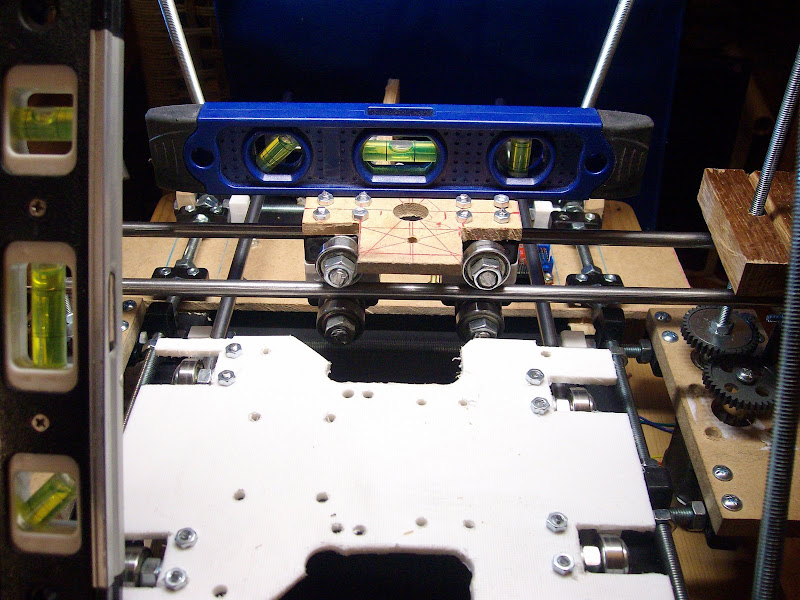
It is not a necessary part for Mendel. I think it might make it easier to square Mendel up. As I am not using belt for the Z axis my steppers hang down an by an extra 16mm.
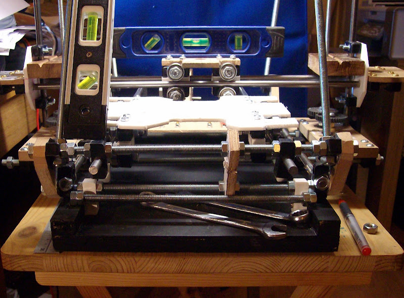
I need Mendel to be easily transportable so it can be picked up like a portable sewing machine set up and put away. Using a base board will keep it square and save from the odd knock. I know its a little Belts and Braces once its nicely set up working, I don't want to have to realign it every so often after its been moved.
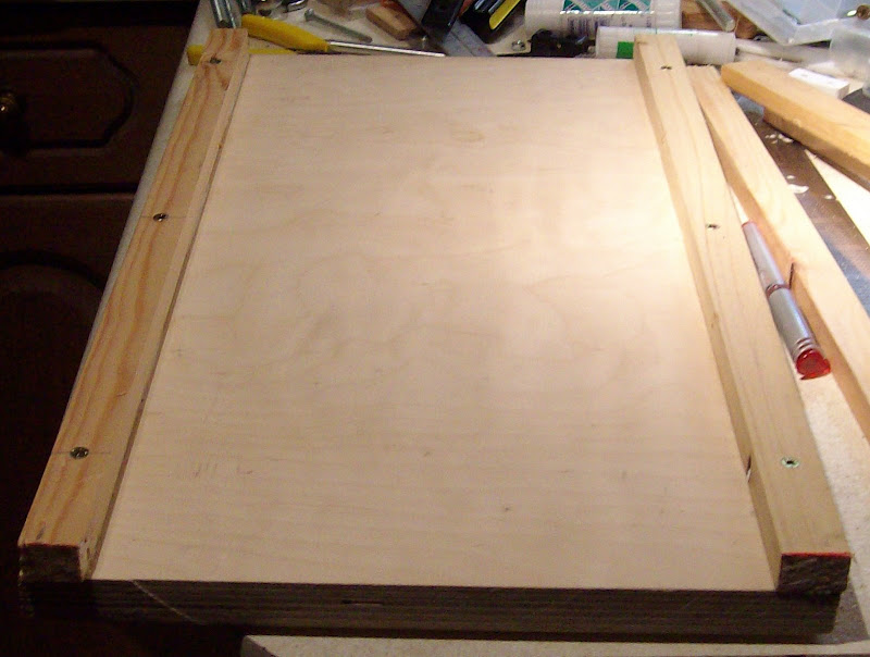
The base board I've used is 18mm Ply but could be OSB board or MDF its is 295mm x 500mm x 18mm.
It has two side bars Mendel is crewed to these side bars at one end so Mendel can be hinged up from the base board to make wiring easier or sort any problems out like flipping a sewing machine up to see its works. The side bars are made from softwood 500mm x 22mm x 14mm softwood. The side bars are screwed and glued to the sides of the board. Then the base board was painted with 30min quick drying black paint. Mendel has left the Kitchen!...
My time was limited today so I built only one stepper controller so not much else was done.
Nopheads suggestion to install the Google tool bar to get a spell checker works great.. thank you.
9 comments:
looking forward to your first print!
Oh so am I !!
"As I am not using belt for the Z axis..."
What are you using for the Z axis if you aren't using belt?
Bob,
Two steppers with gear drive to 6mm threaded bar.
Pictures here of the drive mechanism.
http://repstrapbertha.blogspot.com/2009/12/mendel-build-day-two.html
I think Im going to try to get three bearings running flat against the bar, oiaohm is quite right about the issues re. running on the bevel (sorry, I got your name wrong earlier - I was posting from my iphone and couldnt see the original post!)
One way would be to have two bearings at 90 degrees (relatively easy to do) then one bearing opposite at 45 degrees to the others.
Another way would be to work some way of having the bearings at 120 degrees, possibly bolt them around a large washer or hinge a couple of your plastic blocks so they meet at an angle.
0 90 225 combination not as good as 120 when it comes to wear.
The load between bearings don't work out as even. 120 angle you can rotate the bearings between locations and get good wear. Ie cheat make a rotatable mounting for the bearings so you unlock them rotate them by 1/3 lock them back in.
0 90 225 you wear patten is not as even. And to keep good wear bearing will have to be physically moved around.
But with the live span of bearings in a device like this you might not care. Because running flat on shaft at 90 go to last over 8 years. 0 the verital is going to last over 5 years and the 45 going to last over 3 without rotations.
Now that is using cheep plastic core bearings not ball bearing ones without moving them.
Ie 45 is not exactly a good angle for a bearing. 120 from 0 is about 5 years to eat itself out.
Basically all bearings are going to come up for replacement at about the same time with the 120 and can be streched by rotation because the different places will wear different bits of the bearings. Where they normally don't with 0 90 225. 90 and 225 over lap on there wear locations.
Yes I design to last.
With a 0 90 225 where the 225 is your 45 one. the 45 one can be spring loaded to maintain pressure to hold against the other two bearings. This can reduce vibrations.
For spring loading to take up vibrations the 0 90 225 is better than the 120 split angle. Ie 0 120 240 if you spring load the 240 you have a high risk of pushing out the other side if mounting blocks are not solid.
Everything is a trade off. The 0 90 225 is still way ahead of where you started.
Hopefully this is helpful with designing a mount.
oiaohm has meaning in itself. oiaohm=Ok I Am Over Here Mate/Man Don't worry about getting name wrong it happens. Not like you got my full handle badly wrong.
I wanted to upload an image to this comment, but blogger wont let me!
Ive added a post to my blog instead:-
http://copperrap.blogspot.com/2009/12/evolution.html
With two steppers driving the z axis, would you need two stepper controllers, or can you wire both steppers into one controller (since they need to be in sync anyway)
(On a side note, get rid of silly google toolbars and install Firefox which has a built in spell checker!)
@ oiaohm
That's very good news for me as a repstrap only needs to print one set of Parts which will take less than 40 hours. Then the bearing problem will cease to exist as the bearings will be exactly at 120 degrees using the printed parts.
A rep-strap like this is only a temporay machine that is used to create its own parts to replace the nylon corner blocks completely.
@ Phill..
Wow that looks very good !!
I was in hospital with graph paper trying to sort out two things the design of The shed roof to give light from the north and the 120 degree bearings.
I finished the shed roof design first then got sent home today.
@ Giles
I'm using only one stepper controller running at 2A with the steppers wired in parallel.
Thus they stay in sync.
Post a Comment