I've removed the furniture screw, one plastic block thus reducing the flexing of the whole extruder assembly.
The 1st stepper I used was 4.6 kg/cm or 0.451 Nm torque it had no difficulty.
I'm now using a stepper with 4 times less torque at 1.1 kilogram centimeter or 0.108 newton meter.
The geaing is 26:1 so the extruder resolution should be at least 20 times better than the splined shaft extruder.
The drive has changed from 5mm splined shaft to 7mm gear drive.
Here is a picture of the new extruder.
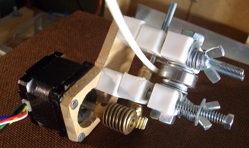
Testing the New extruder causes my ABS stock hanging frame to start bending, as it goes past 4kg of pull.
I achieve 4.7kg of pull before the gripping pulley slips on the shaft or the gear slips on the shaft or on the ABS rod. I.E. tighten the gear the shaft slips with the pulley tighten the pulley the gear slips or the ABS then slips. The Conrad gear or an AK47 "worm" gear are just about the same as each other in my set up no difference.. my "worm" may not be as good as it should thou!
I need flats on the shaft and stronger springs to clamp the bearing into a sharper "worm" pulley.
If the splined shaft gave me 1.7 kg pull this must be not far off Adrian's pukka Mendel extruder.
Getting 4.7kg pull with a low cost low torque stepper using an easy to make drive construction.
Is the best I can do so I'm giving up trying to get a better pull than 4.7kg for now.
My next task is to add a feed guide then marry the extruder to the drive system test then add it to Mendel.
As I need to have two working machines for the show time is short for me to mess around any more trying to get better results that may not be needed. There is still the PID temprature control to get working for both the Ext ruder and Bed yet. I will make drawings once I can prove it works OK if there is time left before the show to do that.
Oh the side effect of the smaller stepper is the whole assembly has weight reduction from 560gms down to 346gms. Just over 200gm weight saving if that will make any difference to performance... ??? I don't know ???
I think I have achieved the best pull I can with out using any RepRapped or specially machined parts.
34 comments:
Looks good. I found greasing the gears gave a lot more torque but I was limited by the motor rather than the grip.
My extruder started squeaking yesterday so I gave it some more grease. I think lubrication will be crucial to making the gears last.
Great stuff. I've been following your progress and nophead's and I'm thinking about trying a double pinch design, see here: http://www.thingiverse.com/iphone/thing:1793
i like this idea, it is good and simple, i am glad to see something like this, out there. i just need to figure out where i can start to find some of the gearing i will need.
i do not see why a person could not do a double pulley system with this setup.
i think lithium grease would work, i don't think the rpm would be fast enough to fling it off.
You can buy meccano gears on eBay easy enough. They are cheap compared to proper engineering gears which can be upwards of £20 each.
Just back from workshop building.. yep I bought my Meccano gears on EBay the worm is a no 32 you can get it in right hand or left hand the one I got is the common one. The spur is 1/2 inch I have a 1" one as well the the 1" is known as a rare gear though and will cost up to £6 in auction the worms gears are Buynow And easy to get at about £3 each. Having quick break to get food Green laser pointer and compass to get Workshop facing due South.
http://bodgeitquicksolapowerdshed.blogspot.com/
Started out a bad day with snow first thing.. nice an sunny now. so must get on.. while it lasts Repraps and CNC's need their new home ASAP.
Thank you for your comments.
The key to getting more grip out of an existing single worm gear design may be increasing the pressure of the nip between idler and worm gear.
There is always a risk that nipping it up tighter though will imprint a flat on the side that is up against the idler bearing.
It could be worth putting a tyre (Push fit, brass tyre, with a channel or work gear cut around it) on the bearing outer to acheive this.
Additionaly if the idler could be driven (maybe an o ring drive belt) This could help increase driven grip too.
This is great, and I am convinced that I have to use this design on my OverlapStrap now.
I am just trying to work out which meccano part number relates to a 1/2" spur gear, I think its no 26?
Anyway, this ebay shop looks reasonable:
The Worm Gear
The Spur Gear
I guess you can buy both parts from the same shop and pay less for shipping?
I use the 40 tooth gear to get a bigger reduction and less pressure on the teeth.
I think it is part no 31.
Damn, I just bought the no 26, and its a lot cheaper than the no. 31 which seems to be upwards of £6
I will try the no 26 and see how I get on, then I will probably have to upgrade to the 31 as nophead said ;)
Just thought, after looking at your piccy some more. Try replacing the springs with rubber ones.
Something like rubber bushings between two washers.
I have found it dificult to source springs that are exactly right, they are usualy too weak or too strong or lastly too expensive/unavailable.
You don't need a long travel on your compresion mechanism. (2 or 3mm will do) Just lots of pressure.
Andy,
Actually with your worm pulley design I find not a lot of pressure is needed on the pinch wheel. It is far less critical than other forms of drive and even works without a pinch wheel at all to some extent.
Just looking at your Pinch less posting Monday, 30 November 2009
Your stepper looks huge compared to the steppers Im using.
or are you using a smaller worm gear.
Measuring My stepper it must be a NEMA 13.5 as it 1.35" square or its a Small/undersized NEMA14 Stepper.
@ Ak47
I think as I have plenty of the Brass Bar left I might try making another one. Nophead noticed that I put a v shaped cut in the second one I made as my original on did not have much of u shape to it.
I didn't have anything other than a 5mm screw to put the blank on to cut the thread. so It was held by wedging the screw in the tool holder and applying presure to the screw with fingers.
Think I need a puka blank holder to cut one like yours and Nopheads.
@ giles
The resolution will not be as good using 1:26 instead of 1:40.
However it will be 26 times better than the Mendel Extruder.
I thought it was better to use the more common spur gear as they are likely to be avalible for other RepRappers and I still had two left over from my meccano set (hate to think how long I've had them..)
Number 31 is called "RARE MECCANO VINTAGE 1" BRASS GEAR WHEEL PART 31 VGC" I got mine in acution for £5:20.
I think my worm is the same as yours but my motor is a NEMA17.
I am surprised that you get enough torque with a NEMA14, a lower gear ratio and no grease.
Don't know If I have enough torque
I only know it can pull/push 4.7Kg.
In fact I was relived that it slipped as the hangman structure was really flexing.. Had visions of being hit on the head as it broke..
Im just looking at the Extruder PID software on Makerbot V1.6 slave.
As I have plenty of K type Thermocouples and only 2 short lead 100k Thermistors trying to decide on the best option. I also only have one AD595 thermocouple amplifier I also have a spare PID controller well its for my old oven but not used yet. Toying with whats the best option Thinking I need to get another AD595
Which do you use Thermocouple or Thermistor on your extruder? if Thermistor do you have a Part number on Farnell I only found ones that look like discreet caps with short leads 15mm or less.
Not realy used Thermistors much only Thermocouples that have nice long heat resistant leads.
I have also been looking at the bowden extruder since reading Adrian's post about Full Color Reprap.
Coloured printing is of no interest to me, but the idea of having the print head detached from the filament drive looks very interesting.
I understand however that the Bowden Extruder suffers from ooze.
Do you (targeted at bodgeit and nophead) think that the wormgear drive could work with a bowden extruder, and also be able to give enough torque to stop ooze?
Yes I am sure it will drive it but I worry that ooze will be worse. I plan to try it in the next few weeks.
Sorry I didn't answer you question about thermistors. I use a thermistor because the electronics are simpler but I do calibrate each one with a thermocouple attached to a multimeter.
I don't think Farnell see the right one. I get them from RS. I use 10K but 100K is better for Arduino http://uk.rs-online.com/web/search/searchBrowseAction.html?method=getProduct&R=4840183
Thank you for the RS link..
I'm kinda lazy have a collection of K type thermocouples with pre-fitted plugs for my temprature meter.
Playing with PID software and easy to make mount for Extruder to heater barrel connection.
More MDF and PVA glue..
Thermocouples probably give a faster response if they have metal to metal contact with the barrel. My barrel isn't insulated though so I would have a problem.
Well according to the Reprap Parts Lister The Thermistor to use has a manufacturers part number of B57560G104F (inferred from the mouser link)
I looked this up on Farnell and bought the following thermistor.
http://uk.farnell.com/epcos/b57560g104f/thermistor-ntc/dp/3878697?Ntt=B57560G104F
probably someone will tell me this is not suitable now :(
Looks like the right part. All I can say is Farnell's search must be crap because if you put in Epcos 100K thermistor you don't get that one in the results.
Phew, thats a relief ;)
What is the cheapest way to do thermistor calibration?
Can it be done with a thermocouple and a multimeter perhaps?
When I make a new extruder I put a rod type thermocouple down the barrel, before it has any plastic in it. I use a multimeter to measure the temperature both hot and cold and get the corresponding ADC values from my firmware and use those to calculate beta and Ro.
I find the thermistor tracks the thermocouple within 2 or 3 degrees after calibrarion.
Thank you Giles for the part number.. and link will be ordering some.
Thanks you Nophead I will employ the Thermocouple down the Welding tip trick.. I had it taped alongside the Thermistor in the Extruder Is a much better place. I agree with you on Farnell's search engine its is pony and trap.
Nichrome cotton covered wire is another item I need for spare heater barrels any ideas USA is going to be too slow.
I don't know if you can get it in the UK. Maybe one of the European reprap supply shops that have sprung up might stock it.
If you are stuck PM me your address and I will post what I have. I don't think I will need it as I use resistors instead.
Anything else you need for the faire ?
I gave these guys a ring and they said they didn't know of anything that would be suitable. (At the time i didn't know that it was fibreglass insulated, which didn't help, because they were thinking more along the lines of oxide based coatings)
Of course Reprapsource now sell insulated nichrome wire so that would be one option.
My heater is made from those vitreous enamel wire wound resistors that nophead uses. I have some of those spare if you want some, and some 3/4" Alu bar to make the holder from.
Could'nt agree more with Nophead. Resistors are the way to go.
Far less hassle.
Oh yes I know power rsistors are great, but you need a block of Al or some thing to mount them in/on.
Mendel is slightly more compact than Darwin and my plastic blocks make a very tight space to fit it in.
I also like the idea of keeping the heated part as small as possible.
I think the Welding tips being only 25mm long keeps the thermal mass extremly low, maybe making it easier to control the temprature with very low heat loses from a very small surface area that can be easily insulated.
Not so easy to make thou.
Thinking of testing the element out of an old hairdrye of Midge's
Need to figure out some high temprature insulation of the wire thou.
Actually if you make the thermal mass small it is harder to control. The RepRap/ Makerbot design using a brass barrel, nichrome and Kapton will heat up in about 12 seconds. The problem is the thermistor cannot respond that fast. The glass beads have a time constant of 7s. That means you get massive overshoot so you need PID control. Maybe a thermocouple would be better in that respect.
PID is not a big problem but you need to tune it. It also requires multiplications and I have nothing higher order than addition in my firmware I beleive.
With a higher thermal mass design like my AL blocks bang bang is sufficient because the rate of change is much slower.
Similarly with the heated AL bed the thermal mass is huge and I get very accurate control with band-bang, only a fraction of a degree ripple.
Let me know if you want a piece of 8mm AL bar.
You can do quick multiplication of binary multipliers by bit shifting.
2,4,8,16 etc
And it is every bit as fast as addition (pun intended)
@AK47.. I know used it in the early 80s with 64bit simultaneous equations on a Z80 in 2ms tunaround for multiple finger entry on touch screens a bit of shifting & used the 8bit multiply and divide functions ... well an upgraded Z80 the Hitachi 64180 12mhz processor was in the touch screen bezel resolution was 1024 x 768.
I was the major contributor to the creation of the patent GB 2133537 A Including all of the design of the hardware and firmware to produce the final product.
Application No GB8332723.9 filing date 08.12.1983
Priority claimed: 16.12.1982 in United Kingdom - doc: 8235896
Patent ceased on 08.12.1993
Post a Comment