Monday, December 14, 2009

Sunday Oops This Computer has hard drive Failure

Delayed more Mendel building on Sunday due to This computer having the main hard drive fail... :-(

So I decided at midday when my Eldest Daughter and BF arrived as it was a dry day my time would better spent clearing the garden for the Solar powerd shed.

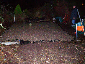
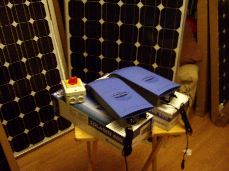
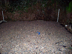
12:30 - 6pm Pictures of 50% 12' x 12' finished Solar powerd shed area 1 ton of gravel used. Special thanks to my eldest daughter and her boyfriend who helped us clear the 24' x 12' area on Sunday and Midges Daughters BF who chain sawed the 4' diameter Pampas grass flat last week.


Hard disk recovery from back up has just finished.

So I am a little behind schedule. with RepStrap Mendel... Thank goodness I had made a back up of Drive C: D: & E: !!!.

Saturday, December 12, 2009

My uninerversal vitamin The Nylon Corner Block

Seeing all the Rep Strap Mendels appearing in many forms. I thought it was time that I made use of My universal Vitamin the ever faithfull Nylon Corner Block ( Fixing Block, Fixit Blocks, Assembly Joint) as I am a very lazy builder of RepStrap machines not completely unskilled as a carpenter or metal worker and one who likes the whole concept of KISS.

For those who don't live by KISS it is the Acronym for Keep It Simple Stupid I like this principal and that of spending as little as possible to achive my goal. Also currently being without income is another contibuting factor to this need.

So from watching and pausing the excelent overview Videos then examining the drawings and pictures made by triffid.hunter and : swighton I have been able to build my low cost low tech version of Mendel using a few  Nylon Corner Blocks I will attempt to build the Mendel frame from scratch in a day/weekend here goes. a pictorial build. Start time Saturday 12 December 8:30am.


From Blogger Pictures


From Blogger Pictures


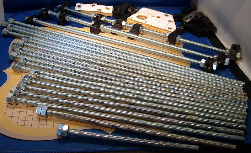
The Esential Build tool for making any kind of Repstrap with Nylon Corner Blocks a build Gauge so all bars are Eactly the same size Ideal for Kebab Quality control.



In use.. Making the plain side bar Two required.



Making the motherboard and extruder mounting side bar 2 required.
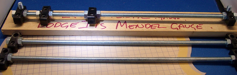


 Making the bottom bar with Stepper controller mounting board 2 Required Note both pairs with extra Nylon Corner Block made as mirror images of each other.
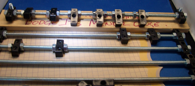


All the Kebabs made Time for a quick Coffee Break and two slices of Toast.. The I will see if the Sides are Equilateral when mounted on the blocks.

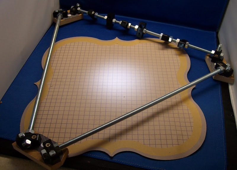
Wey Hey it worked.. well it looks  Equal onlt time will tell thou.


Out of focus sorry Detail of the Nylon Corner Block mounting using one wood screw to hold it together.


Now to make the other side.. Oh mistake no 1 above I did not use the Mother board side bar it became obvios as I had two for the next Mendel side.. Opps.
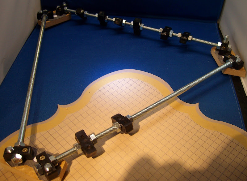


And two together..
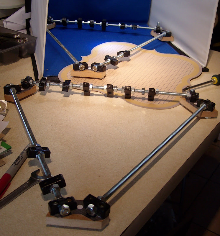


Next to put the two together... off to read the Mendel assembly guide... not sure which is the next bar to use..

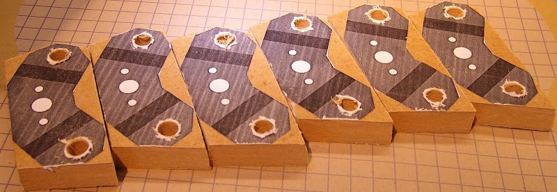
Hmm Slight change to Mendel design  Nylon Corner Block Mendel Needs Legs Have used White Nylon Blocks to make the Legs stand out I have also made Nylon Block type 3 wich has an 8mm hole for the slider bar and one of the two holes drilled out to 8.5mm.
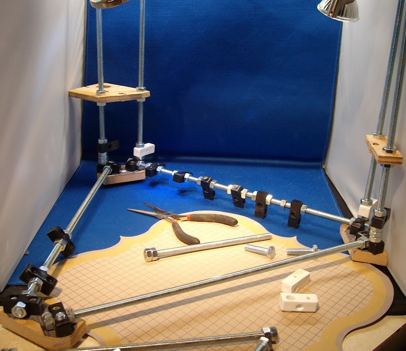


Build so Far Sarurday 16:42 build time 7.92 hours Tea break time as Midge is back from Art Class.
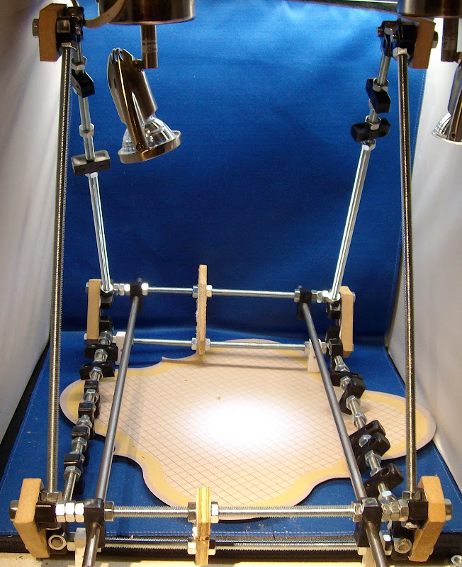


Time to make some more wooden bits for the slider rails for the Z axis as the bars are no diffrent from the corner blocks I will make two more corner blocks and fit the forth type of Nylon corner block this will have a the single hole drilled out to an 8mm hole to grip the Z slider rods and will be screwed to these two new wood bits.

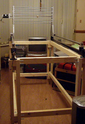
The build will not fitt in the photo booth now! It also needs to be squared up as it has a 2mm wobble the same as a Darwin needs Squaring up the wobble on Mendel seems less than the two Darwins I built so its looking good.
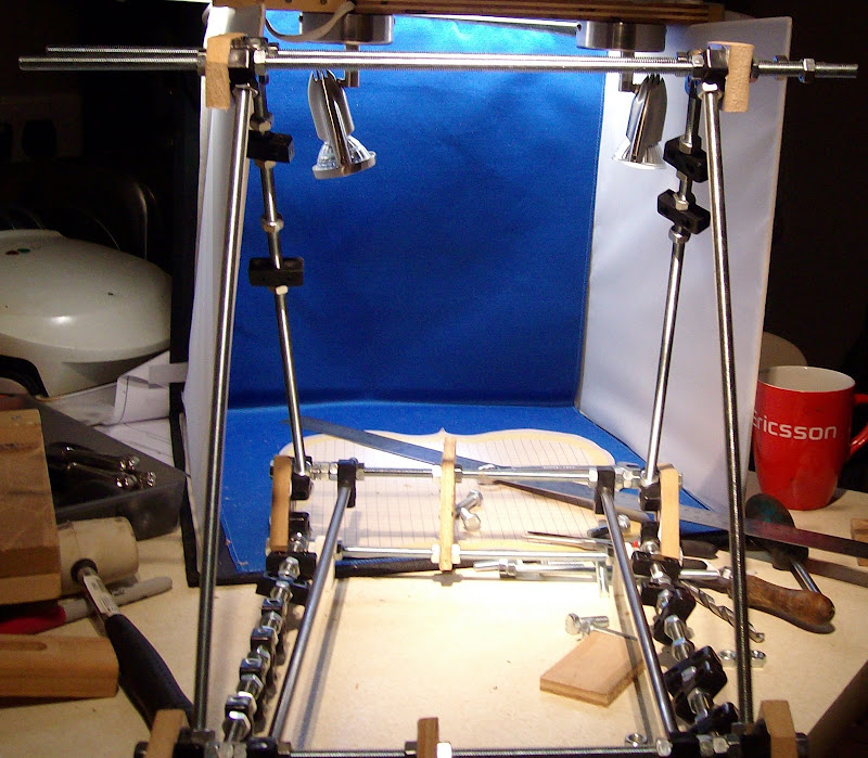


Basic assemble of the frame completed now I just need to add the X and the Y Axiss to finish..

Jobs to do Make X carridge assembly Make motor mounts for Z and X and sliders. Make Stepper controller mounting board Make motherboard-Extruder controller mounting board. Make build platform board.

Saturdat 17.49 Build time almost nine hours and a break for Merlin.

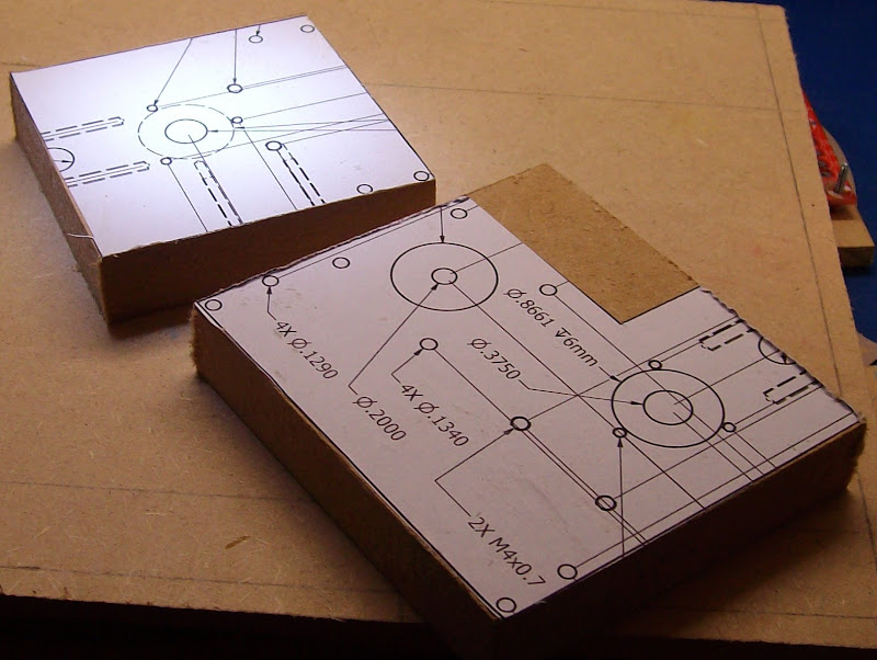
Made the following PCB mounting boards and drilled the 8 4mm holes in each to suit the Nylon corner blocks. Layed out the PCBs and drilled the other holes to mount the PCBs.

Motherboard mounting board 290mm X 98mm x 6mm
Stepper mounting board 380mm X 80mm x 6mm
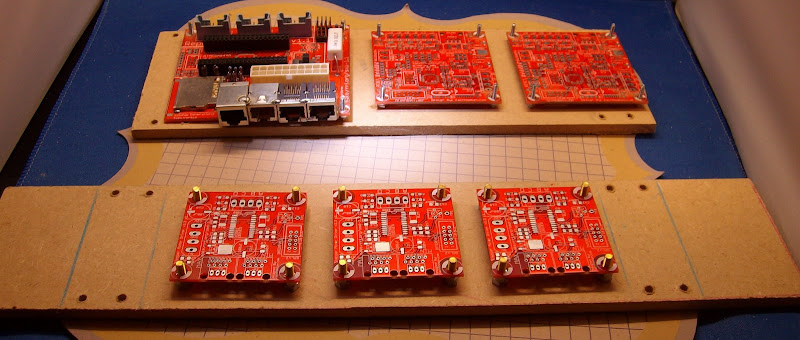


Made the other thick pannel boards
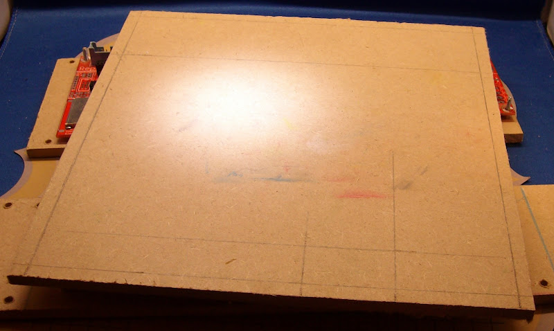
Print base board 230mm X 200mm x 6mm


Z slider mounting pieces.


Midnight Saturday 11 hours spent on the Mendel build End of Day one.
Thursday, December 10, 2009

Experiments with off the shelf Amtel processor boards

RepRap Mother Board


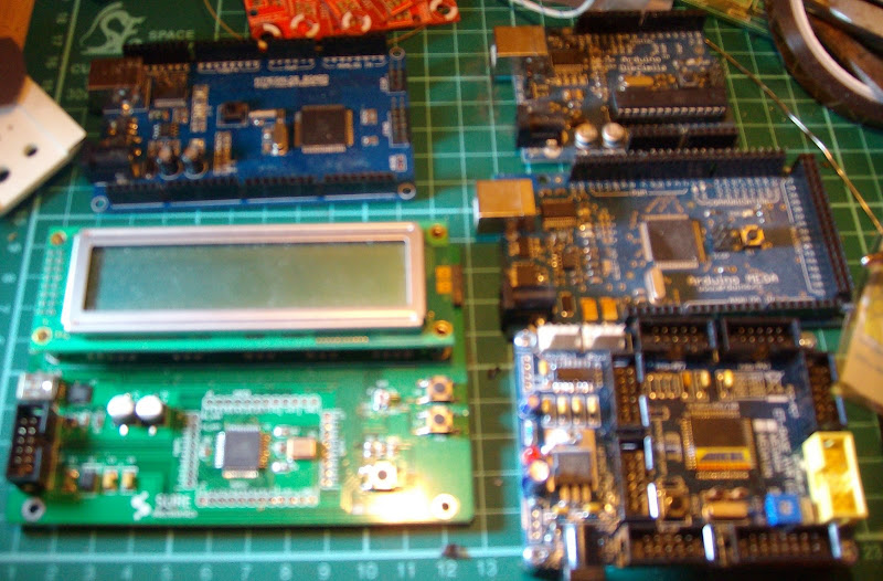
A collection of Other off the shelf Amtel Processor board.


From top left to right we have an ATMEGA128 board then an Ardrino Decima board with an ATmega328 chip fitted making it now Arduino Duemilanove.ATMEGA16 Board with LCD display Aurdrino Mega with Mega 128 Board below.

Over the next month I will be investigating the best way to make use of these Boards on my REPSTRAP REPRAP Builds.
The ATMEGA16 will only be used for PID type control or display purposes I have several of thes boards that I will be using in my Solar power projects. It might also turn out to be a nice way to control an Extruder on the Bertha CNC machine though providing Extruder temprature and flow rate date on its LCD display. All the others are candidates to controll a full RepRap Strap Machine.
First I'm going to build one of my 2.1 extruder controllers to get my extruder working then I can begin.

Ahhh just found out that the spell checker is not present on the new blogger editor!! so please excues the dyslexic spelling.


Saturday, December 5, 2009

My first Extruder build and testing

I am all caught up on every ones Blogs caught up on all of the Forum posts with a Saturday with Midge off doing a Life Drawing class.

So without much else that I want to do today I'm going to make and test my Extruder !!!!
OK 1st tidy untouched work area!!! Charge 6 AAA batteries for temperature meter find the bits.

With 4/5 RepRap/CNC Machines I can fit it too and 2kg of ABS its about time I actually finish making an Extruder.

So here is where I start putting the bits I have already made together some over a year or more ago. New batteries in camera.

Pictures of the parts I have already made:-


Measuring the resistance of my meeter leads 0.3 ohms I have striped the back the insulation of 300mm of nichrome wire to 285mm measured as 6 ohms with the lead resistance subtracted from the measured 6.3ohms.

Using two brass inserts and the two screws from a 5A chocolate block connector with a red and a black moulded 4mm skt with 105mm of wire on each I have twisted together the12mm ends of the Nichrome wire and one of the power cables at each end of the heater element. Then screwed the two brass screws down very tight then I soldered this connection. I re checked the resistance of the heater element circuit between the brass connectors still at 6 ohms.

From blogpics


I then wrapped Kapton tape around each connection. I then taped the Black connection to the Peek insulator with Kapton tape. Wrapped a short length 22swg around the welding tip give an edge to wind the nichrome wire against wound the nichrome on ending just before the flat on the welding tip. Taped the red end of the element to the peek insulator then taped the nichrome coil to the welding tip.
Positioned my K type thermocouple on to the flat on the welding tip and taped with more Kapton tape. I then wrapped a layer of high temperature self amalgamating tape around the welding tip assembly and around the Peek insulator.

Ready to test... @ 5.16V and 804mA the measured temperature seems to be sitting at 200 C. (This was incorrect as the Thermocouple was reading low using the thermocouple supplied with the meter meant 200C was measured with 6.89V @ 1043mA on the element)


Little problem with the Maplin K type thermocouple and my Temperature meter as the meter goes out of range with the thermocouple at 200 C. So I have an Incompatibility with the meter from Deal Extreme and the Maplin K type thermocouple here seems to work ok with the meter tho. Nope it did not I reverted to using the Thermocouple supplied with the meter from this I will calibrated the maplin thermocouples in the Ardrion cct. Having now got an extruder heater that works it wont be long now.

The high temperature self amalgamating tape (pipe repair tape) from B&Q works ~Using 4 Cir clips to hold the Peek insulator to the aluminum angle works well. Next Jobs sorting out calibrating the thermocouples and control electronics. Trying to get the extruded plastic smaller ~Using a 0.6mm welding nozzle the extruded plastic was 0.9mm considerably more than I expected.

Photo are not very good getting a close up in focus with my camera was impossible.

I ran the Extruder on and off for at least an hour or more hand feeding 3mm ABS.

Sunday, October 25, 2009

Off subject as been busy gardening.

By gardening I really mean clearing the ground ready to build the Solar powered Shed/Workshop.


With a foot print of 24' x 12' its a big space shrubs have gone Pampas grass is going though a bit worried it might decide to grow again.

Also some very tall grasses that look like Bamboo I believe it to be a very tall 8' to 10' tall Miscanthus that looks like bamboo that is in three huge clumps. Its Murder to dig up my old spade just bent as I tried. I have thoughts of this rampant grass forcing its way through the floor of the shed.. more pictures of the garden before BodgeIt .

Any Ideas on how to ensure these grasses do not try to grow again are welcome as I think just covering them with membrane and gravel will not suffice.

Monday, September 28, 2009

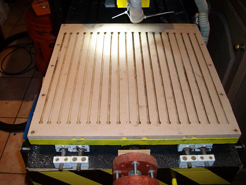
Bertha cuts her own T slot work clamping base


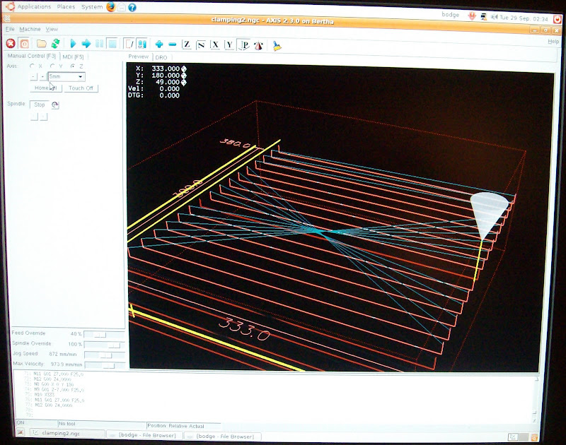
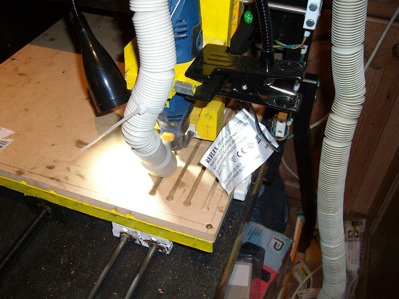
Using the Dremel Key hole router bit 655 not quite its intended use but it works well once I figured out that 10mm a min was the best speed for a 7mm deep cut and almost the slowest speed on the look alike avoided MDF burning smell. so it takes 30Min's per slot to cut there are 19 slots ie every 20mm. I also learn a little G code in the process.


The process has identified that I forgot to put the collar back on the X axis drive shaft when I added the two extra runner on the X axis. Oops so there was a 2mm difference between the start point of the first X T slot to the start of the last X T slot. As the Slots are only for Clamping stuff down is no big problem tho.


The bigger problems are:-

Finding a reliable way to set spindle speed on the look alike.

Finding a way to stop the filters blocking on the hover when cutting MDF.

Modifications required:

Fit the Collar on the X axis.

Upgrade Y and Z Axis's to have motor couplers, bearings and collars like X instead of Plastic tube and tie wraps... Coupling... Thou neither the Y or Z axis had any measurable error like the X had.. the solution for X is more mechanically stable thou..

An electronic switch to turn the spindle on and off.

An electronic switch to turn the hover on and off.

Maybe make some kind of spindle speed detector to have complete control of spindle speed.

Wednesday, September 16, 2009


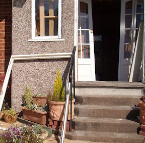
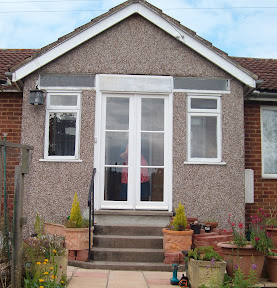
A busy weekend in Gloucester making a Double door frame and fitting new hard wood doors to my Mom's house. So not much rep rapping or CNC~ing etc.. Any way here is a quick up date on Bertha and Big Bertha the projects.. Some brief details on the Big Bertha project blog. Slightly earlier than anticipated due to the success of Bertha.


Also last weekend I added the 2 extra runners on the X and Y axis of Bertha.


Bertha completed over 110,000 lines of G code using the pic to G code function of EMC2 I made the mistake of clicking on invert image so I stopped the G code some 120,000 lines early. lessons learnt dont make the first real job for your CNC a big one a 9.4 MB Gcode file is > 200,000 lines of Gcode set the feed rate higher than 120mm a min and a cut of depth 0.1mm.

So the carve a logo exercise ended up as one long soak test.
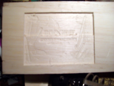
Great result though Bertha did not fall apart it did not lose position and the low cost look like a Dremel did not fail. Other lessons learnt you need a fan for the X Axis motor or run it at < 2A. An aborted Bodge It Logo around 100mm x 73 mm~ 3-4mm deep. Note the invert function takes the regular G code and reverses the code order not a good idea as it re cuts seach layer.


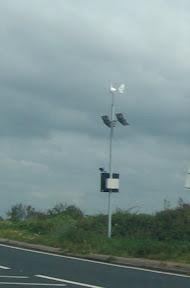
Oh and not forgetting the picture of the Wind and Solar powered speed caution signs seen on roads around Gloucester.

Thursday, September 3, 2009

I love it when a plan comes together!

Things arrive from around the world together amazing!!!.

To see more go here:-

The deliverys arrive.. pictures of the bits.


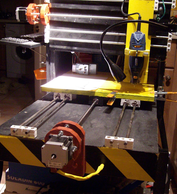
Pictures of the rebuilt Bertha now as a CNC

A work in progreess with axis transion speeds of > 30mm /s

I'm working on making the as yet unsupported trapezoidal spindle drive shaft to make it so that its supported with bearings, this will allow a much higher axis transition speed. I'm also will be improving the rigidity of the Y axis by adding two more 8mm y Axis slide bars the beauty of using the nylon blocks as the mounting method has saved around £70 the cost of a traditional CNC slide system.


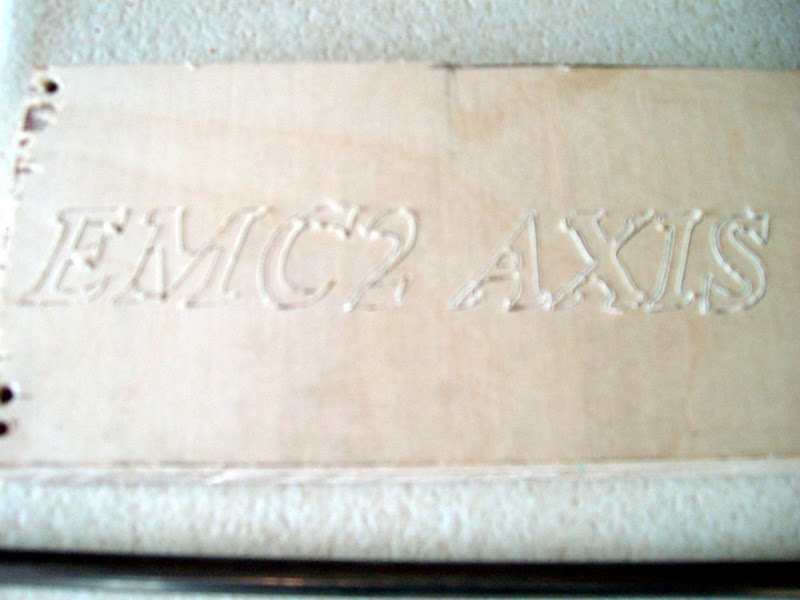
Here is a picture of the first test routing performed.. using a cone shaped dremel bit no 125


I am still having intermitent problems with the Z Axis home opto sensor despite ex-changing the sensor for another one and changing the parallel printer port input pin from 12 to 13, using USB double screend cable and adding high and low value capacitanc to the 5v supply pins on the Opto sensor PCB.
I have also reduced the length of the sensor cable run that is spiro wraped with the stepper and dremel power cables. curently run out of ideas to solve the problem.
Correction its a Dremel look alike from Aldi.. I do have a puka Dremel as well as several other imitations. I also have a giant 700W dremel type tool from the B&Q P Pro range this will be used on Big Bertha .. Yes a 700w with a small collete pin chuck just like a dremel.

More pictures of Bertha and its insides on the BodgeITQuickTools blog.

Ps Midge just asked why I didnt sand the test piece to make it look better. It is as it is off of Bertha.. I didnt use a small dremel 105 engraving bit as I did not know if Bertha would work hence it is a rough cut in the beach ply that is 0.02mm deep (If my stepper configuration settings are correct ) I dont know the speed of the cutting either but it was finished /done in less than 2 min.