Wednesday, September 16, 2009


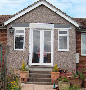
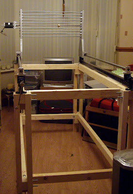
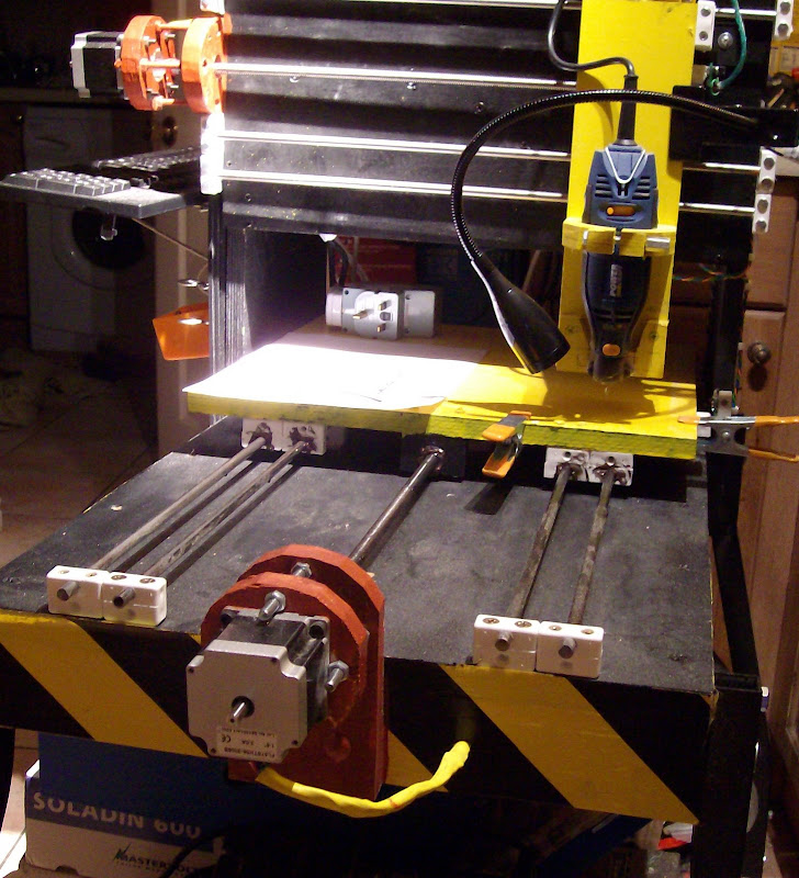
A busy weekend in Gloucester making a Double door frame and fitting new hard wood doors to my Mom's house. So not much rep rapping or CNC~ing etc.. Any way here is a quick up date on Bertha and Big Bertha the projects.. Some brief details on the Big Bertha project blog. Slightly earlier than anticipated due to the success of Bertha.


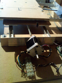
Also last weekend I added the 2 extra runners on the X and Y axis of Bertha.


Bertha completed over 110,000 lines of G code using the pic to G code function of EMC2 I made the mistake of clicking on invert image so I stopped the G code some 120,000 lines early. lessons learnt dont make the first real job for your CNC a big one a 9.4 MB Gcode file is > 200,000 lines of Gcode set the feed rate higher than 120mm a min and a cut of depth 0.1mm.

So the carve a logo exercise ended up as one long soak test.
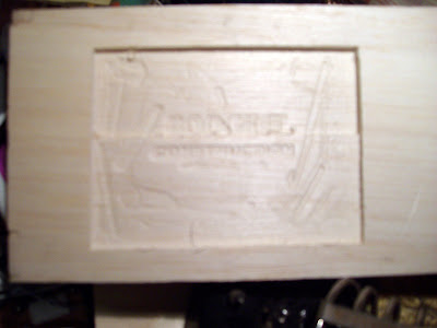
Great result though Bertha did not fall apart it did not lose position and the low cost look like a Dremel did not fail. Other lessons learnt you need a fan for the X Axis motor or run it at < 2A. An aborted Bodge It Logo around 100mm x 73 mm~ 3-4mm deep. Note the invert function takes the regular G code and reverses the code order not a good idea as it re cuts seach layer.


Oh and not forgetting the picture of the Wind and Solar powered speed caution signs seen on roads around Gloucester.

Thursday, September 3, 2009

I love it when a plan comes together!

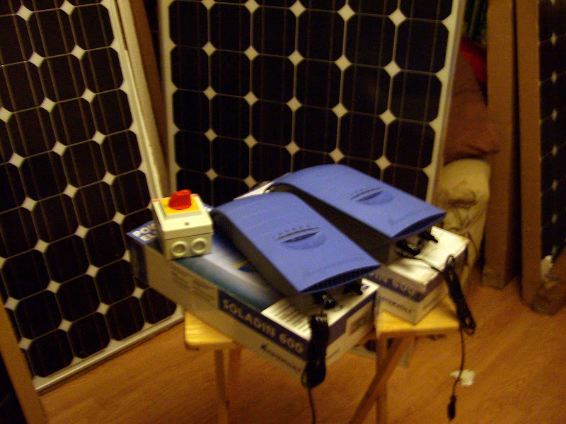
Things arrive from around the world together amazing!!!.

To see more go here:-

The deliverys arrive.. pictures of the bits.


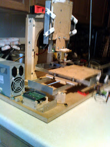
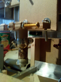
Pictures of the rebuilt Bertha now as a CNC

A work in progreess with axis transion speeds of > 30mm /s

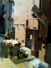
I'm working on making the as yet unsupported trapezoidal spindle drive shaft to make it so that its supported with bearings, this will allow a much higher axis transition speed. I'm also will be improving the rigidity of the Y axis by adding two more 8mm y Axis slide bars the beauty of using the nylon blocks as the mounting method has saved around £70 the cost of a traditional CNC slide system.


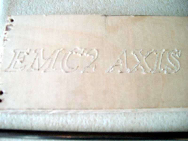
Here is a picture of the first test routing performed.. using a cone shaped dremel bit no 125


I am still having intermitent problems with the Z Axis home opto sensor despite ex-changing the sensor for another one and changing the parallel printer port input pin from 12 to 13, using USB double screend cable and adding high and low value capacitanc to the 5v supply pins on the Opto sensor PCB.
I have also reduced the length of the sensor cable run that is spiro wraped with the stepper and dremel power cables. curently run out of ideas to solve the problem.
Correction its a Dremel look alike from Aldi.. I do have a puka Dremel as well as several other imitations. I also have a giant 700W dremel type tool from the B&Q P Pro range this will be used on Big Bertha .. Yes a 700w with a small collete pin chuck just like a dremel.

More pictures of Bertha and its insides on the BodgeITQuickTools blog.

Ps Midge just asked why I didnt sand the test piece to make it look better. It is as it is off of Bertha.. I didnt use a small dremel 105 engraving bit as I did not know if Bertha would work hence it is a rough cut in the beach ply that is 0.02mm deep (If my stepper configuration settings are correct ) I dont know the speed of the cutting either but it was finished /done in less than 2 min.

Saturday, August 15, 2009

X and Y axis sliders method 3 ONLY for belt or ball chain drive.

I am total amazed by this one I expected this to have more friction than the skate bearings and for it to have a lot of play.. neither is the case it is also very very much lighter as it has not got 32 skate bearings. I cant belive how simple the X & Y mechanisims are now and its £16 cheaper to buy..


X & Y Sliders method 2 is for using Bike chain

After testing method 3 with Bike chain I have found that you must use this method.
Its a bit of a catch 22 ~ toothed belt rus great with method 3 and is closest to a printed Darwin.
However with bike chain the extra weight causes too much friction and skate bearings are needed. Skate bearings and bike chain are cheaper but in the long run you will need to buy toothed belt. I will continue to look for an inexpensive reliable method of making ball chaine drive pulles as this solves the catch 22 by eliminating toothed belt.

X and Y axis sliders method 2 tyring to avoid drilling big holes in wood and keeping it simple to make. Making the sliders out of Nylon corner fixing blocks.


Here are the full details of the construction. X & Y Sliders method 2

Sunday, March 22, 2009

originalFree drive belt gears for Z axis using LL025XML (RRRF Belt)

Lost posting recoverd...

For those in the UK/US taking an ASDA/Wal-Mart Blue milk bottle top filled with poly morph/Capa creates a Z pulley with the correct pitch of gripper plastic to mate with the RRRF drive belt (LL025XML). Complete with a dimple in the middle to drill the 8mm hole for the Z axis. I've not finished experimenting but it looks very good.


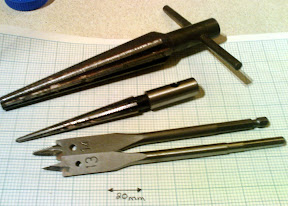
Tools used.
Design change for X and Y gears so all are made in simple ply mould for all three by making the drive shaft from 6mm studding.

By using a short length of 8mm Aluminium tube as a bearing insert to fit the 6mm studding in a standard skate bearing. The new 6mm size drive can replace the 8mm drive shaft on Repstrap Darwin

Mould assembly
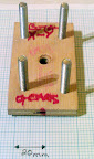
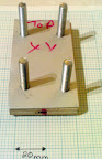


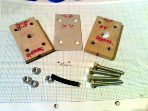
The XY belt length for mould is 0.1mm x 400steps = 40mm.
Cut 40mm of belt starting at a tooth & ending just before a tooth thus giving 20 teeth.
The hole size required to make the mould is (40mm/3.142) + 2*0.64 mm [belt height] = 14mm.
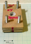
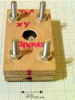
I took 2 pieces of ply 75mm X 44mm held them together drilled a 6mm hole through the middle put a 6mm nut and bolt through them marked the sides with marker pen. Drilled 6mm holes in each corner 15mm in from each edge. I took the ply apart marking the tops with felt pen... I took the top piece and used a 13mm wood bit to drill out the middle hole (use a 14mm drill if you have one.)
Using my big tapered reamer and the 40mm of belt I adjusted the hole for a perfect fit. I sanded all of the internal edges of the new hole fitted the belt. This made great gears but when I drilled out the drive shaft hole it was slightly off centre. So off to B&Q to get a 14mm wood bit & remade the Top plate. I also decided to make an Aluminium plate to go between the top and bottom ply plates to make a nice flat finish on the end of the gear. I found using a cheap friction style G clamp with a penny washer produced a better finish to the top of the gears. I used a 1 pint Christmas pudding bowl to heat the water to temperature in the microwave.
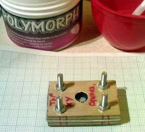


Filling the Bowl 3/4 pint of water & Micro waving for 2.5 mins in a 900w microwave gave the right temperature for the Polymorph. I found measuring a milk bottle top full of Polymorph was just right for making one gear.
I used a plastic fork to squish the Polymorph granules together and remove them from the hot water. Once drained you can handle the plastic (test it first as you don’t want to burn your puddys) push into the top of the mould level it off put penny washer on top and clamp down with G clamp leave for 10 mins remove clamp and washer. Un-bolt mould remove aluminium plate ensure polymorph has cooled to white colour re-bolt the ply parts flip mould over & drill 6mm hole un bolt mould pop the gear out carefully peeling of the length of belt you have one nice looking gear.
The first gear you make will pick up any wood dust so put the first gear to one side.
re-assemble and repeat this time the gear is perfect, so make 2 more.
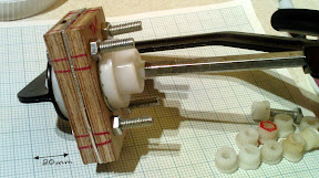
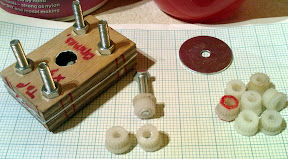
The finished gears are a tight fit on threaded rod so screw the gears on. I put a washer on either side of each gear on the Y axis. The X axis can be fitted to the X stepper using supper glue and some force to fit it I adjusted the hole with a small tapered reamer first.
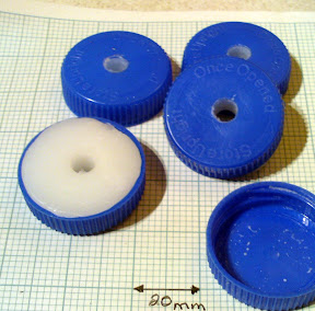


The milk bottle top gears have 64 teeth. The Z resolution remains at 1mm / 400steps =0.0025mm as this is governed by the thread of the drive shafts not the pulley size.

Lost posting recoverd...
Wednesday, January 14, 2009

Quick update on the two RepStrap builds.

The DIY Repstrap started out using the pipe CNC idea using copper pipes and easy fit connections. Looking at it one day I just thought it would bee much cheaper in MDF with 2x1 and more robust.
Having already discovered the 13" long Y axis was not big enough I decided If I was to change the Y axis to 15" I might as well remove the copper hence we get the 2x1 and MDF low cost DIY repstrap.

Blogger Pictures


Using £12 stepper motors that seem quite happy with a 6 Kg load on the work table.

Problem with using the lower cost steppers motors they get very hot when powered continue sly. I had already bought a Maplin infra-red thermometer for checking the extruder temp.
pointing this at the itty bitty steppers showed me they were sitting at 70C burn your puddys hot.

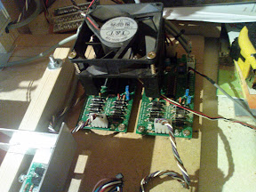
Looked at the standard Arduino decided Pin 15 would do to switch all of enable pins on the RRRF stepper controllers.


Last weekend was spent playing getting the Arduino and Sanguino controllers working correctly with the RepStrap Machines now this appeared to be a bit of a black art at first getting a version of the firmware to run correctly there seem some serial coms race conditions, I must say seem as I have not bothered to investigate the actual problem. One set of documents have the data bits parity and stop parameters set labelled incorrectly.
Any way reading a Forum post by Chris Meighan I downloaded the zip file and ran the package Luckily Chris had chosen the same Arduino pin to enable the steppers.
All the problems were resolved by using the New, improved G-code firmware for RepRap the code is nicely commented and compact. I installed the latest Windows RepRap Host from Adrian the only problem seen using the Host software is some kind of resolution problem with the Z axis where instead of 400 steps per mm you need to set this to 200 don't know why yet. The firm ware from Chris seems to be correct in stand alone mode, not yet down loaded the source for the Host to investigate. Spent a lot of time playing with G code files and Windows RepRap host SW.

Next Job finish the extruder order ABS to play with not sure about using HDPE yet.

Thursday, November 6, 2008

Extruder notes

I have decided to make at least two extruder's one for each machine, both using the direct dive as Nophead has done. Both will be using Peek not PTFE as it seems to work ok for the meta lab machine.


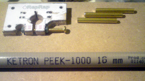
I received my length of Peek - 1000 16mm today just need to develop a means of cutting it straight and drilling a central hole to tap without a lathe.Also figuring out how to start the die threading the brass rod correctly. This has encouraged me to only thread the part that will screw into the Peek.

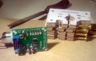
I will be using the rrrf magnetic shaft encoder on one extuder and Looking at this locking-solarbotics-gm3-clutch as another little differential modification.


The other little problem on Bertha is to try to cut the noise it makes. to be continued